

Help. Basic Stamp Aborting Program on HV project
 JW Smythe
Posts: 12
JW Smythe
Posts: 12
I'm looking for a little help, I hope someone can help me figure out what the heck is going on.
I'm trying to use a Basic Stamp (Homework Board) to control an ignition coil for something I'm experementing with. Ok, it's just fun to play with high voltage. [noparse]:)[/noparse]
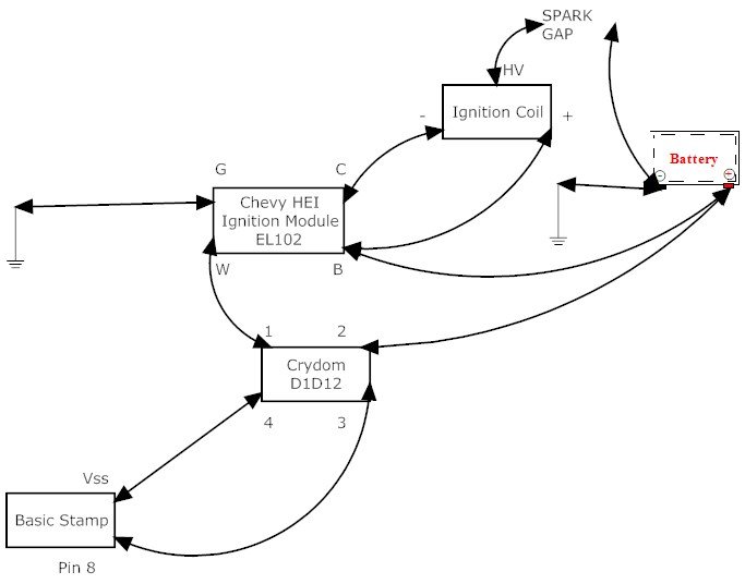
Attached is a diagram of my setup, but you can get the general idea from the text below too.
The major problem that I'm running into right now is that the basic stamp stops running while I'm testing. Sometimes it goes fine, and I can get a nice long series of sparks (hundreds to thousands of cycles). Sometimes, I get one spark, and the 'power' light on the BS goes off. If I hit the 'reset' button on the BS, it starts back up with varying degrees of success.
I believe I have the stamp isolated enough to not incur damage from the rest of the process.
Since I'm playing with some oddball things, I'll describe everything.
--- Begin BS Program
'{$STAMP BS2}
'{$PBASIC 2.5}
I VAR Word
D VAR Word
I = 5
DEBUG "Pulse ", DEC I, CR
FOR D = 1 TO 1000
HIGH 8
PAUSE I
LOW 8
PAUSE I
NEXT
DEBUG CR, "END", CR
--- End BS program
This gives me a 1000 cycles, of 8ms on, 8ms off, so roughly a 16 second runtime. I can go down to about I=3. If I go to I=2, it gives me some intermittent sparking. If I go to I=1, I don't get much of anything.
I just adjusted the FOR loop, to make the duration longer or shorter, as I pleased.
This *DOES* work. It *DOES* make sparks as expected. Unfortunately, after a while, it stopped behaving correctly. It'll give me anywhere between 1 and 3 quick sparks, and the "power" light will go off, but the debug screen will never say "END"
The stamp itself is running from a 9V battery (it's a homework board). I thought maybe I wore the battery down too much, but it does the same thing with a fresh battery (or two)
The rest of the system is running on a 12V battery from my lawnmower (think car battery, but a little smaller). It still has plenty of juice in it.
The Crydom D1D12 is a Solid State Relay. I'm trying to isolate the BS from the rest of the fun as much as possible. Obviously, there's a good chance of making something smoke (I've smoked a lot of parts so far). as I've found out, the SSR doesn't like the kick back from the ignition coil (lost 2 to figure that out)
On the SSR,
3 low voltage + (source)
4 low voltage - (source)
2 high voltage + (load)
1 high voltage - (load)
The Chevy HEI Ignition Module is simply the old standard module to make the ignition coil in a car work, using 12V from the ignition key, and a 12v signal from a sensor to say "spark now". Depending on the car, it could be a crank trigger, or a trigger inside the distributor.
G is ground. The case is also grounded.
W is the trigger input (the BS in my case)
C is to the ignition coil "-"
B is the 12V input from the key. This also leads up to the ignition coil "+"
So basically, the ignition module is another SSR, pulsing "C" to ground the low voltage side of the ignition coil.
The coil I'm using is an "Accel SuperCoil", which their site indicates puts off 45,000 volts max.
The way an automotive ignition coil works is, you put DC in one side. It builds up a nice healthy magnetic field on the iron core. When you drop the voltage, the field drops, the coil wants to discharge somewhere, which is hopefully out the HV side through the spark gap (spark plugs in a car).
I found out the hard way that the Crydom doesn't like the surge coming back at it.
We also played with hooking it straight up to a battery, and just tapping one of the wires to the battery terminal. It occasionally made a spark at the gap, but usually it made a very large spark at the battery.
I found plenty of diagrams online, which showed various capacitors and/or resisters, but I didn't have much luck with them. (search "Ignition Coil Driver" on Google)
Both the SSR and the Ignition module are on heat sinks. The SSR doesn't get warm at all. The ignition module does get warm, but never hot. I used a nice old PII (Slot 1) heatsink, so there's plenty of surface area for it to cool.
So the question again. Why would the stamp abort it's program? I have it set about 2 feet away from the spark gap. All the components in order on my floor (sitting on plywood) are:
BS --> SSR --> Ignition Module --> Ignition Coil --> Spark gap
I'm not getting the stamp close enough to the spark gap for trouble, and it's electrically insulated by the ignition module and SSR. My only thoughts on it are maybe EMP from the spark, but I would have expected the problems when I first started playing. Maybe something is overheating? Maybe there's a ghost inside all of it, messing with me. [noparse]:)[/noparse]
The original purpose for this was to try to play with the "cold fusion" stuff. Not professionally or academically, just for fun. [noparse]:)[/noparse] I had absolutely no result from it in the water. At least 12VDC makes bubbles. There are plenty of pictures online showing other people doing it, with different equipment. I'm guessing that I'm not putting enough amps through it to do much of anything.
While it was sparking, I tried various configurations. Both electrodes in the water (no visible response). + over the water, - in the water, sparked to the water very nicely, but nothing visible in the water. Both electrodes out of the water made a nice spark. I did manage to get it to spark from about 1/4" to 3"
I was trying to reconfigure it to make a Jacobs Ladder. I was already running into the problem of the stamp shutting down. By the time I hooked up the rods for the ladder, I was only getting a few sparks and then it was shutting down. I did find out that styrofoam and plastic do conduct (probably on the surface), but with only getting a very few sparks, it was less than encouraging for me to try different insulators to hold the rods up.
I was also attempting the mythical "Stanley Meyer" water fuel cell results. I can't say that any particular frequency had any amazing results, but I'm still playing with that one. From almost everything I've seen online, most people debunk his stuff without ever attempting it. I'm keeping an open mind and trying it before I say it does or doesn't work. Why not. I have the equipment set up now, all I'm wasting is my spare time.
I was tempted to post this in the completed projects section, but I won't until I get this bug worked out.
I look forward to your suggestions and comments.
I'm trying to use a Basic Stamp (Homework Board) to control an ignition coil for something I'm experementing with. Ok, it's just fun to play with high voltage. [noparse]:)[/noparse]
Attached is a diagram of my setup, but you can get the general idea from the text below too.
The major problem that I'm running into right now is that the basic stamp stops running while I'm testing. Sometimes it goes fine, and I can get a nice long series of sparks (hundreds to thousands of cycles). Sometimes, I get one spark, and the 'power' light on the BS goes off. If I hit the 'reset' button on the BS, it starts back up with varying degrees of success.
I believe I have the stamp isolated enough to not incur damage from the rest of the process.
Since I'm playing with some oddball things, I'll describe everything.
--- Begin BS Program
'{$STAMP BS2}
'{$PBASIC 2.5}
I VAR Word
D VAR Word
I = 5
DEBUG "Pulse ", DEC I, CR
FOR D = 1 TO 1000
HIGH 8
PAUSE I
LOW 8
PAUSE I
NEXT
DEBUG CR, "END", CR
--- End BS program
This gives me a 1000 cycles, of 8ms on, 8ms off, so roughly a 16 second runtime. I can go down to about I=3. If I go to I=2, it gives me some intermittent sparking. If I go to I=1, I don't get much of anything.
I just adjusted the FOR loop, to make the duration longer or shorter, as I pleased.
This *DOES* work. It *DOES* make sparks as expected. Unfortunately, after a while, it stopped behaving correctly. It'll give me anywhere between 1 and 3 quick sparks, and the "power" light will go off, but the debug screen will never say "END"
The stamp itself is running from a 9V battery (it's a homework board). I thought maybe I wore the battery down too much, but it does the same thing with a fresh battery (or two)
The rest of the system is running on a 12V battery from my lawnmower (think car battery, but a little smaller). It still has plenty of juice in it.
The Crydom D1D12 is a Solid State Relay. I'm trying to isolate the BS from the rest of the fun as much as possible. Obviously, there's a good chance of making something smoke (I've smoked a lot of parts so far). as I've found out, the SSR doesn't like the kick back from the ignition coil (lost 2 to figure that out)
On the SSR,
3 low voltage + (source)
4 low voltage - (source)
2 high voltage + (load)
1 high voltage - (load)
The Chevy HEI Ignition Module is simply the old standard module to make the ignition coil in a car work, using 12V from the ignition key, and a 12v signal from a sensor to say "spark now". Depending on the car, it could be a crank trigger, or a trigger inside the distributor.
G is ground. The case is also grounded.
W is the trigger input (the BS in my case)
C is to the ignition coil "-"
B is the 12V input from the key. This also leads up to the ignition coil "+"
So basically, the ignition module is another SSR, pulsing "C" to ground the low voltage side of the ignition coil.
The coil I'm using is an "Accel SuperCoil", which their site indicates puts off 45,000 volts max.
The way an automotive ignition coil works is, you put DC in one side. It builds up a nice healthy magnetic field on the iron core. When you drop the voltage, the field drops, the coil wants to discharge somewhere, which is hopefully out the HV side through the spark gap (spark plugs in a car).
I found out the hard way that the Crydom doesn't like the surge coming back at it.
We also played with hooking it straight up to a battery, and just tapping one of the wires to the battery terminal. It occasionally made a spark at the gap, but usually it made a very large spark at the battery.
I found plenty of diagrams online, which showed various capacitors and/or resisters, but I didn't have much luck with them. (search "Ignition Coil Driver" on Google)
Both the SSR and the Ignition module are on heat sinks. The SSR doesn't get warm at all. The ignition module does get warm, but never hot. I used a nice old PII (Slot 1) heatsink, so there's plenty of surface area for it to cool.
So the question again. Why would the stamp abort it's program? I have it set about 2 feet away from the spark gap. All the components in order on my floor (sitting on plywood) are:
BS --> SSR --> Ignition Module --> Ignition Coil --> Spark gap
I'm not getting the stamp close enough to the spark gap for trouble, and it's electrically insulated by the ignition module and SSR. My only thoughts on it are maybe EMP from the spark, but I would have expected the problems when I first started playing. Maybe something is overheating? Maybe there's a ghost inside all of it, messing with me. [noparse]:)[/noparse]
The original purpose for this was to try to play with the "cold fusion" stuff. Not professionally or academically, just for fun. [noparse]:)[/noparse] I had absolutely no result from it in the water. At least 12VDC makes bubbles. There are plenty of pictures online showing other people doing it, with different equipment. I'm guessing that I'm not putting enough amps through it to do much of anything.
While it was sparking, I tried various configurations. Both electrodes in the water (no visible response). + over the water, - in the water, sparked to the water very nicely, but nothing visible in the water. Both electrodes out of the water made a nice spark. I did manage to get it to spark from about 1/4" to 3"
I was trying to reconfigure it to make a Jacobs Ladder. I was already running into the problem of the stamp shutting down. By the time I hooked up the rods for the ladder, I was only getting a few sparks and then it was shutting down. I did find out that styrofoam and plastic do conduct (probably on the surface), but with only getting a very few sparks, it was less than encouraging for me to try different insulators to hold the rods up.
I was also attempting the mythical "Stanley Meyer" water fuel cell results. I can't say that any particular frequency had any amazing results, but I'm still playing with that one. From almost everything I've seen online, most people debunk his stuff without ever attempting it. I'm keeping an open mind and trying it before I say it does or doesn't work. Why not. I have the equipment set up now, all I'm wasting is my spare time.
I was tempted to post this in the completed projects section, but I won't until I get this bug worked out.
I look forward to your suggestions and comments.
683 x 536 - 29K
Comments
·
·· On one hand it seems like you’re experiencing typical EMI/RFI problems inherent with generating large voltages.· I am curious though…You said the Power LED goes out on the Stamp…Which board are you using?
▔▔▔▔▔▔▔▔▔▔▔▔▔▔▔▔▔▔▔▔▔▔▔▔
Chris Savage
Parallax Tech Support
I was wrong on the light, it's the "Running" light. [noparse]:)[/noparse] The board I'm using is the HomeWork board, rev B. with bundled book and a few components.
http://www.parallax.com/detail.asp?product_id=90005
It was an impulse buy. I probably wouldn't have ordered one online before, but since it was at the store and I was buying stuff, I couldn't resist. I'm glad I did now.
Anyways, it does stop a running program, while it's sparking. I am tending to think it's electrical interference, except it's weird. It seems to work perfectly for a little while, but then degrades rapidly. It will do a run for a few seconds, and quickly go down to handling one spark before it stops. Even if I'm in a DO ... LOOP. I'm avoiding those, just in case I get into trouble with it running.
I'm leaving the whole mess off for the night, to see how it behaves again in the morning.
Do you have any suggestions for protecting it from interference? Would another board handle it better? I am running it with the serial cable attached to my laptop (about 8' away from the spark gap). I haven't seen any problems on the laptop, but I'm sure the case is protecting it better than the exposed board. I'm sure all the wires make for a great antenna to bring in any interference.
You might try decreasing the pulse width and using slower rep rates,and see if it does better.
Example: 1ms pulse width, 10 pulses/sec
HIGH 8
PAUSE 1
LOW 8
PAUSE 100
I think the pulse width in an automobile is much less than a millisecond, while the rep rate changes with RPM.
Perhaps the ignition module doesn't like to be on for 50% of the time, as you have it now.
DaveG
You MUST have adequate power filtering to your BS2. Especially if the automotive coil is not loaded. I once designed an electric fence
using an automotive coil that needed to "drive" 2 miles worth of fence. Without the coil loaded, my PC would reboot 25ft away, so there
are some serious EMI/RFI conditions that need to be considered when using automotive coils.
▔▔▔▔▔▔▔▔▔▔▔▔▔▔▔▔▔▔▔▔▔▔▔▔
Beau Schwabe
IC Layout Engineer
Parallax, Inc.
Well, one thing happened, which was weird. The AC power on the porch is on a GFI outlet. The GFI outlet itself is in my garage (maybe 50' away?), but will trip the outlet on the back porch (where I'm working). For some reason, it tripped.
The weird part of that is, I'm not using A/C power for anything with the HV. The stamp is running off a 9v battery, and the spark gap from a 12v battery. The only thing plugged in is my laptop (that I'm writing this message from)
Dave, I had planned with playing with the pause cycle, but hadn't gotten around to it. It seems to not mind going I*? or I/? I did it all the way to I/1000. [noparse]:)[/noparse] I don't know if the stamp interprets it right, but it seemed to make a difference in the tone.
I've found how to reproduce it. It looks like it's probably EMI, unless the stamp just can't keep up with going this fast.
This is what I'm using now (and variations of):
'{$STAMP BS2}
'{$PBASIC 2.5}
I VAR Word
D VAR Word
I = 10
DEBUG "Pulse ", DEC I, CR
HIGH 14
FOR I = 1 TO 10
DEBUG "Pulse ", DEC I, CR
FOR D = 1 TO 1000 / I
HIGH 8
PAUSE I
LOW 8
PAUSE I / 10
NEXT
NEXT
LOW 14
DEBUG CR, "END", CR
It's not completely stopping though. I have an LED on pin 14. When I first started playing, it was on pin 8, but then there wasn't enough power left on pin 8 to run the SSR. The LED will stay on, but the program won't continue running.
It seems to not like somewhere between I=3 and I=7. It'll either get stuck, doing short pulses at the current rate, restart the program (most of the time), or just stop.
I switched the outside FOR to go from 20 to 1. It's funny, stuck at 5 right now. I guess now we know that you can confuse this BS with a remote spark gap. [noparse]:)[/noparse]
While I was writing that last line, it was pulsing at 5, but then finally reset, starting back at 10 (going from I=10 to I=1)
Ok, this was all fun. I'll take some pictures of the setup, and dismantle it. [noparse]:)[/noparse]