Shop OBEX P1 Docs P2 Docs Learn Events
External oscillator not working — Parallax Forums

External oscillator not working

joshrljoshrl Posts: 10
edited 2006-10-19 21:37 in Propeller 1
Hi,

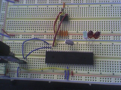
I'm having a problem getting an external oscillator to work with my prop. I am able to run programs with the internal clock fine, but when I switch to the external clock (by setting _clkmode, and _xinfreq) the program doesn't seem to run (LED's don't light). I've tested the oscillator on the propeller demo board and it works fine so I don't think its the oscillator. If its important, the oscillator I am using is the 5.00C5X from Digikey. I've also tried several other oscillators with no luck. Here is the source code and a picture of the curcuit.

CON
  _clkmode = xtal1 + pll16x 'comment out these 2 lines and the program runs fine
  _xinfreq = 5_000_000
  
  Delay = 3_000_000
  
PUB Toggle
             
  dira[noparse][[/noparse]16]~~
  dira[noparse][[/noparse]17]~~
  dira[noparse][[/noparse]18]~~
  repeat              
    !outa[noparse][[/noparse]16]
    waitcnt(Delay + cnt)
    !outa[noparse][[/noparse]17]
    waitcnt(Delay + cnt)
    !outa[noparse][[/noparse]18]
    waitcnt(Delay + cnt)


Is it possible there is something wrong with the prop. chip?

Thanks,

Josh
500 x 375 - 124K

Comments

  • Phil Pilgrim (PhiPi)Phil Pilgrim (PhiPi) Posts: 23,514
    edited 2006-10-16 20:44
    Josh,

    I couldn't find that part on DigiKey's website. But your photo shows a crystal, not an external oscillator. A crystal should work, though, as long as it has some built-in capacitance (15 -20pF should be enough). It might also be that there's too much internal capacitance and cross-coupling in your wireless breadboard. Breadboards are often unsuitable for things like oscillation circuits for that reason. If all else fails, you could try bending the Propeller's crystal leads upward and soldering the crystal directly to them.

    -Phil
  • Beau SchwabeBeau Schwabe Posts: 6,568
    edited 2006-10-16 20:48
    joshrl,

    Nothing wrong with your code, but you do need current limiting resistors of at least 100 Ohms for your LED's.

    ▔▔▔▔▔▔▔▔▔▔▔▔▔▔▔▔▔▔▔▔▔▔▔▔
    Beau Schwabe

    IC Layout Engineer
    Parallax, Inc.
  • Mike GreenMike Green Posts: 23,101
    edited 2006-10-16 20:56
    You can't use "xtal1 + pll16x" when using an external oscillator tied to XI (pin 30). I think you have to specify the "_clkmode" bits explicitly as %0_1_1_00_111. This enables the clock input circuitry and the PLL, sets xinput for an external clock input to XI, and enables the PLL at 16x. It's not clear that this is allowed (external clock + PLL), but try it.
  • joshrljoshrl Posts: 10
    edited 2006-10-16 21:19
    Mike Green said...
    You can't use "xtal1 + pll16x" when using an external oscillator tied to XI (pin 30). I think you have to specify the "_clkmode" bits explicitly as %0_1_1_00_111. This enables the clock input circuitry and the PLL, sets xinput for an external clock input to XI, and enables the PLL at 16x. It's not clear that this is allowed (external clock + PLL), but try it.

    I tried setting _clkmode to %0_1_1_00_111 but I get a compile error: "Invalid _clkmode specified". xtal1 + pll16x does work on the demo board which seems to be using an external crystal, so not exactly sure why it would be a problem. thanks.
  • Mike GreenMike Green Posts: 23,101
    edited 2006-10-16 21:28
    Sorry, I read your description rather than looking at your picture. When you mentioned external oscillator, I thought you were referring to an external oscillator, not an external crystal (they're different). If the problem is too much capacitance, try using "xtal2" or "xtal3" instead of "xtal1". Look at the Propeller Manual on page 29.
  • Phil Pilgrim (PhiPi)Phil Pilgrim (PhiPi) Posts: 23,514
    edited 2006-10-16 21:29
    Josh,

    I don't see any bypass caps in your photo. You need at least one of 0.1uF or more right next to the Propeller. Cut the leads short. It would be best to connect the Vdd and Gnd pins on both sides, too, with a cap on each side. While you're at it, bypass the EEPROM supply as well.

    -Phil
  • joshrljoshrl Posts: 10
    edited 2006-10-17 14:51
    I added resisters and bypass caps, see attached. No change though, the program still doesn't run with external crystal.

    -josh
    500 x 375 - 135K
  • Phil Pilgrim (PhiPi)Phil Pilgrim (PhiPi) Posts: 23,514
    edited 2006-10-17 16:31
    Josh,

    Your aluminum electrolytics, while certainly helpful, don't really qualify as bypass caps. What you need are some 0.1uF ceramic caps inserted into the breadboard right next to the Propeller chip — not out on the supply rails. Be sure to cut the leads as short as possible. I can't say that this will solve your oscillator problem, but it is good practice and will eliminate that variable.

    Which regulator are you using, BTW? Most regulators require an output cap placed very near the regulator for stability. Check the regulator's data sheet for the value and type. It will specify two things: capacitance and ESR (equivalent series resistance). In most cases, a 10uF tantalum will satisfy both requirements.

    Finally, be sure to try Mike's suggestion to increase the crystal drive, in case breadboard capacitance is the issue.

    -Phil
  • joshrljoshrl Posts: 10
    edited 2006-10-17 17:11
    Sorry if this is silly question, but where should the caps go on the board? I'm assuming from VDD to VSS as close the propeller as possible?
  • Mike GreenMike Green Posts: 23,101
    edited 2006-10-17 17:14
    Yes.

    The 0.1uF ceramic caps are intended to handle very very short power surges on the order of microseconds to nanoseconds so lead length is important.
  • Phil Pilgrim (PhiPi)Phil Pilgrim (PhiPi) Posts: 23,514
    edited 2006-10-17 17:31
    Sorry, Josh, it's not a silly question at all, and I should have been clearer. The regulator output cap should also go from Vdd to Vss. Also, check the regulator data sheet for an input cap requirement. Usually a 0.1uF cap from the input terminal to Vss will suffice, if any is needed at all.

    -Phil
  • joshrljoshrl Posts: 10
    edited 2006-10-17 19:35
    Tried the ceramic caps, still no go.... Also tried soldering onto a perf board to avoid the breadboard and still no go. I'm wondering if it is indeed the propeller that is somehow not working.

    thanks for all your help.

    -josh
  • cgraceycgracey Posts: 14,206
    edited 2006-10-17 19:54
    Josh,

    Can you check to be sure that your 3.3V supply is steady? It would be good to look at it on a scope and be sure that the voltage does not dip down when the crystal is engaged. This might be tripping the brownout detector which·resets the chip. Also, try connecting BOEn high and putting a 10K resistor between RESn and VDD. That will disable the brownout detector and pull RESn high.
    joshrl said...
    Tried the ceramic caps, still no go.... Also tried soldering onto a perf board to avoid the breadboard and still no go. I'm wondering if it is indeed the propeller that is somehow not working.

    thanks for all your help.

    -josh
    ▔▔▔▔▔▔▔▔▔▔▔▔▔▔▔▔▔▔▔▔▔▔▔▔


    Chip Gracey
    Parallax, Inc.
  • cgraceycgracey Posts: 14,206
    edited 2006-10-17 19:56
    Josh,

    From your picture, it looks like there is no cap connected to the output of the 3.3V TO-220 regulator. It needs to go between the GND and Vout pins. Also, an input cap might help to (between Vin and GND).

    These caps need to plug into the same contacts that the regulator uses - right next to it!

    ▔▔▔▔▔▔▔▔▔▔▔▔▔▔▔▔▔▔▔▔▔▔▔▔


    Chip Gracey
    Parallax, Inc.

    Post Edited (Chip Gracey (Parallax)) : 10/17/2006 8:01:50 PM GMT
  • joshrljoshrl Posts: 10
    edited 2006-10-17 20:33
    Chip Gracey (Parallax) said...
    Josh,

    Can you check to be sure that your 3.3V supply is steady? It would be good to look at it on a scope and be sure that the voltage does not dip down when the crystal is engaged. This might be tripping the brownout detector which resets the chip. Also, try connecting BOEn high and putting a 10K resistor between RESn and VDD. That will disable the brownout detector and pull RESn high.


    Unfortunetly, we have no scope but we did add 10k resistors b/w RESn and VDD. We also did the same for BOEn, not sure if this is what you meant though. Finally, we also added the 10uF Cap to Vout on regulator. Still no go.
    240 x 180 - 19K
    500 x 375 - 148K
  • joshrljoshrl Posts: 10
    edited 2006-10-17 20:43
    Not sure if its relevant but we also have a 4Mhz oscillator that we could try. Does anyone know how to wire up the 4 pins?
  • Peter JakackiPeter Jakacki Posts: 10,193
    edited 2006-10-17 21:28
    Not sure if this is your problem josh but if I remember correctly the breadboard contacts are exposed of the bottom of this breadboard type. From one of your photos it looks like you have the breadboard sitting on a BLACK mat of some sort. If this is a carbon style anti-static mat then that will surely be your problem as the high resistance will kill the oscillations of the crystal circuit.

    Since you circuit seems to work fine with the internal 12MHz the only other problem could be:
    a) the crystal itself
    b) poor regulation at higher current/frequency (decoupling caps!!!)
    c) Does pin 40 (RxD) need a pullup resistor in the absence of a signal to drive it? (I see a bare header)
    d) dunno

    This is just a guess mind you.

    *Peter*
  • Phil Pilgrim (PhiPi)Phil Pilgrim (PhiPi) Posts: 23,514
    edited 2006-10-17 21:38
    If the pins of your 4MHz oscillator are on the corners of a 14-pin DIP pattern, they'll be numbered 1, 7, 8, and 14. Pin 14 will be Vdd, but that may have to be 5V, dependiing on the oscillator. If so, and if it has a CMOS-style output (as opposed to TTL) you will have to provide a voltage divider on the output to limit it to 3.3V. Pin 7 will be Vss, and pin 8 will be the output. Some oscillators use pin 1 as an enable, so you may need to strap it (through a 10K resistor) to either Vdd or Vss.

    The output voltage may be difficult to measure without a scope. If it's a CMOS oscillator, you can probably just attach a voltmeter and double the reading to estimate the value for "high". If it's a TTL oscillator, that might not work, since the "low" may be higher than zero.

    -Phil
  • Graham StablerGraham Stabler Posts: 2,510
    edited 2006-10-17 21:41
    Crystals can have rather thin legs, there is a chance you are not making a connection with the breadboard, something to check, might be worth doubling the legs over if they are long enough. That's if they do seem loose.

    Graham
  • Phil Pilgrim (PhiPi)Phil Pilgrim (PhiPi) Posts: 23,514
    edited 2006-10-17 21:43
    Graham, that's a very good point!!!
  • joshrljoshrl Posts: 10
    edited 2006-10-19 17:53
    We got a new Propeller Chip and it works! Must have been something wrong with the chip...Thanks for all you help, it all good information anyway.
  • Peter JakackiPeter Jakacki Posts: 10,193
    edited 2006-10-19 21:37
    Well it's possible that the props crystal oscillator was damaged by esd but I never trust the "new chip works, must have been something wrong with the old one" until I plug the old one back in again to double check.

    *Peter*
Sign In or Register to comment.