

Question on 74HC595 Shift Register
 tigershark35
Posts: 60
tigershark35
Posts: 60
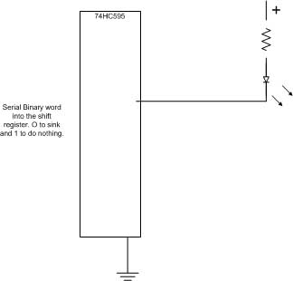
Hi.· I need to turn on and off a number of leds and I want to do it by loading a binary number into a shift register. The question is, if the 595 has a 0 on a pin, will it sink current from the LED to ground as shown in this diagram. I have a matrix led that will need to have the rows and columns turned on and off to combine red and green LED on a bar graph.· I know I can turn on the + columuns using the shift register, but I need a way to turn on and off a sink the current of the rows.
Thanks JG
Thanks JG
324 x 310 - 18K
Comments
Datasheets from 4 mfgs [noparse]:http:[/noparse]//www.datasheetcatalog.com/datasheets_pdf/7/4/H/C/74HC595.shtml
From the datasheet for ON semiconductors version MC74HC595A
I could not find ratings for the Philips version in their datasheet.
"DC Input Current, per Pin ± 20 mA"
"DC Output Current, per Pin 35 mA"
▔▔▔▔▔▔▔▔▔▔▔▔▔▔▔▔▔▔▔▔▔▔▔▔
Think outside the BOX!
Here is the LED that I am using. I plan to get a voltage measurment and then disply a battery voltage dropping using this LED bar graph. I will have to have some Red green and amber similiar to what is shown. I will have to strobe it rapidly and thought that I could have shift register on the top for the columns sourcing one col at a time, and at the same time I would change the value in a shift register to sink the row(s) that will correspond to the Col being activated. I guess I could use transistors on the rows run by the output of a shift register. I can load two bytes to the registers in series and then latch and do it again for the next row/col, etc. That is about the only way I have been able to figure out how to do it.
http://www.primeled.com/2005_Brochure/7.html
Thanks