

Project with leds and relays
 jcferguson
Posts: 86
jcferguson
Posts: 86
I have my radio-control video-sending robot project at the "make it" stage thanks to a lot of help from this forum.
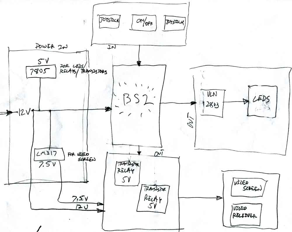
I have posted below something like a flow chart for my transmitter circuit and wonder if anyone could take a look?
A 12V power supply will drive the BS2 (and a video receiver through a relay), this 12V power supply will also be regulated to 5V (for the transistor/relays and LEDs) and 7.5V to drive a small video screen through the other relay.
I have an on/off momentary contact switch - the BS2 waits for this switch while blinking a single LED and then allows the user to "play" for a few minutes, counting down the remaining time with the 8 LEDs on the uln2803. The video screen and video receiver will also get power through their respective relays when this switch is toggled. So... the idea is that when the switch is toggled, everything comes on and starts a countdown, then it all goes off and waits for the next toggle. This is because the piece will be interactive in a gallery setting - and this will give people a logical amount of time to play before handing off the controls to the next person.
I also plan on a 22000 UF capacitor on the input 12V as this made the video quality less noisy.
Is this a logical progression for my circuit?
Thanks!
Carlos
1000 x 794 - 41K
Comments
I think I will try to make a circuit diagram to avoid silly mistakes, but just wanted to see if there were any obvious things I was doing wrong. Maybe it would be better to drive my relays with another ULN2803 instead of separate transistor/relay combinations - but I suppose it is the same either way...
I wondered about driving the BS2 from 5 V but wasn't sure if it would run off that low of a voltage - since I thought the voltage regulator on board would need more than 7V to regulate a steady 5V. Or is there a different spot to plug in a 5V source? I think there must be after reading what you have written below.
Thanks again for any ideas. I really appreciate the help. I should say everything has worked so far on my breadboard, but I am using the professional development board and need to do a bit more work to get it working on the little bs2 carrier board that will fit in the controller and robot. What do you do with those pins that are sticking up next to the BS2 anyway on that board - is there some header that is supposed to fit there - do I solder directly to those pins? They look like they are supposed to be functional in some way!
http://www.parallax.com/detail.asp?product_id=27120
Thanks again, I really appreciate the help,
Carlos
ULN2803's are fine, separate transistors are fine. The ULN2803's are convenient when you have several devices you want to drive.
The pins that "stick up" on the carrier board are for attaching "jumpers" or other off-board connections or as test-points for attaching a voltmeter or logic analyzer or oscilloscope. You can solder to them if it's useful. I rarely used them when I would build projects on the carrier board.
If you're using the voltage regulator on the BS2, you must NOT use more than 50 mA total. That includes the 5 mA or so the BS2 uses itself. If you're using the 'external' linear regulator, you have 1.5 Amps to use (1500 mA).
▔▔▔▔▔▔▔▔▔▔▔▔▔▔▔▔▔▔▔▔▔▔▔▔
Truly Understand the Fundamentals and the Path will be so much easier...
What monitor are you using? I am looking for a small 5 to 7" for a robotics project myself.
Are you doing this wireless?
JG
As far as reverse polarity protection goes, can I put a large diode in-line with the positive voltage to the entire circuit? I had this project working about a year ago (but with a radio control set instead of a basic stamp) and then hooked up power backwards and smoked a lot of things before I figured out why things were (literally) smoking. Don't laugh. The diode will clamp the power if it is hooked up backwards, right?
I have a couple of these that came with a mix of diodes: 1N6286A. Is there a reason not to do this?
Thanks,
Carlos
I am using a "PSone" screen made by sony, you can find them on ebay or elsewhere on the web. They are about 40-60$, 5", 7.5 volt, good color and clarity. There is a lot of information out there about pinouts and modifications.
Carlos
The diode will work as long as you take into account the voltage drop across the diode (typically 0.7 volts). So, if you want your circuit to see 5V then you need to be able to present 5.7V with the diode in line.
▔▔▔▔▔▔▔▔▔▔▔▔▔▔▔▔▔▔▔▔▔▔▔▔
Truly Understand the Fundamentals and the Path will be so much easier...
Ok, I have three more questions --
1
I have a 5v relay that is dpdt and contacts are rated for 2A. Can I use this one relay to drive two different devices with different voltages? It looks to me like I should be able to drive my video receiver with one side of the relay with 12V and the video screen on the other with 7.5V, triggering both with one BS2 pin. Is it better or safer to use two separate pins? I want both devices on and off at the same times.
2
How do I know how much resistor to put between my stamp pin and my tranistor (3904)? Do I want as much resistance as possible? I saw in another post that someone uses 330 Ohm with this transistor to saturate the pin (which I assume means that as much current as possible will flow across the collector and emitter?) I also see in WAM that something on the order of 66K Ohm is used in an example. My understanding is that this resistor will control how much current gets to the base pin and in so doing control how much current goes across the collector-emitter. Don't I just want to saturate this pin then, and how do I figure how much resistance will do this?
3
I ordered some opto-isolators after seeing this as a suggestion for protecting the stamp in another post. Is the correct setup to drive the optoisolator directly with the stamp pin, then drive a transistor with the optoisolator and then drive the relay with the transistor?
Thanks again!
Carlos
2) Most similar switching transistors have current gains from 30 to 50. If you put in 10ma, you will get 300 to 500ma of collector current (maximum). A 330 ohm resistor should produce maybe 15ma. Typically, with +5V supply, a microcontroller will produce about 4.4V for a HIGH level. Subtract 0.7V for a base-emitter voltage and you have 3.7V. With a 330 ohm resistor, thats 3.7/330 = over 11ma.
3) Most opto-isolators consist of an LED (which needs a series resistor when driven by a Stamp pin just like any LED) and a photo-transistor. Most of these phototransistors can drive a small relay directly. As always, check the datasheet for maximum collector current.
My relay needs more current then my opto-isolator could provide, so I put a transistor between them...
I have my "control panel" working and have breadboarded the servos and video camera/transmitter that will ride on the remote rover. It all works so far, I am beginning to think I might make my deadline of next Thursday (!).
A couple more questions.
1
The rover-bot runs on a slot-car like track - with power coming from copper tape on the track. This 12V power will need to be regulated to 6V for the video transmitter and servos and 9V for the camera (I thought I would either use the 9V for the BS2 or the 12V directly). Is a linear power regulator the best way to proceed here? I get a lot of heat from the regulators as it is now set up and wonder about other schemes - switching regulators? Bigger heat sink?
2
I am considering putting a relay on the rover to turn on and off the camera/servos/transmitter for times when the thing sits in a gallery unused for a while. The camera draws current and makes heat (as per question one above) and I would rather it sit there cooling between users. I am not sure about the code for this. Right now, the receiver (rover) code is simply an endless loop to read values from the RF transmitter/receiver and send out the values to the servos. What would be the best way of "breaking" this loop to turn off the relay? I thought about sending something like 1,1,1 out from the transmitter when it is dormant and putting an if/then line in the receiver loop code. When 1,1,1 was detected by the receiver, I could turn off the relay, then jump to another loop that would wait for some value other than 1,1,1, then turn on the relay and go back to the original loop?
3
Can I use the relay to turn off power ahead of the linear regulators - or do I need to turn on and off power after the regulator - or does it matter?
Thanks,
Carlos Ferguson
3) Some regulators have logic level on/off inputs which make it trivial to control the power with a microcontroller pin.
2) Easiest thing to do is to keep a count of the number of times through the loop and reset the count to zero every time a code is received from the receiver. When the count gets bigger than some empirically determined value, turn off everything that you don't need to keep running and leave it off until you receive a code, any code which will cause things to get turned on again. The "turn-on" code is otherwise ignored.
Today's questions - relay back-voltage protection - Reading about relays, everyone says to "put a diode in reverse over the coil"
This makes sense to me, and so I put a LED in reverse - just to see - and in fact, get a little flash everytime the relay shuts off.
My question: is this LED enough to protect my transistor and opto-isolator in this situation (the coil draws 30ma when on) or do I need a different diode, and if so, how do I choose which? A 1n1004?
Thanks! Thanks!
Carlos
TI has some switching regulator modules that are designed to "drop in" in place of standard linear regulators. I don't have a link to them, but do a web search for them.
I mostly build my stuff from kits and tend to use "wall-warts" for power supplies, so I couldn't give you first hand knowledge, but I have built and used some standard switching regulator circuits (from the manufacturer's app notes) that just happened to be pre-packaged in kit form and they work fine.
So what is actually happening here to flash the led when the relay goes off? Is it right that when the relay closes the voltage spikes briefly, but in reverse - and then my LED which is also connected in reverse (anode to negative side of coil, cathode to positive side so it is off when the voltage is flowing) burns up this extra bit?
I am running my relay with 6V instead of the 5V rating (so I don't have to set up a regulator just to provide the voltage for the coil), but this means that my 6V regulator is both powering the relay and switched by the relay. Is there a problem with this?
Whew! I hope that explains it satisfactorily.
I don't know what you mean by a 6V regulator. Do you mean a regulator whose input is 6V from the same supply as the relay or what?
If so, sure, you can power the relay and the regulator from the same 6V power supply (if you have enough current available).
Thanks for the explanation Mike!
Carlos
One thing I am not sure how to fix - my RCTIME values "drift" when I start up the controller from cold. Is this due to the capacitors? The pots in the joysticks? The basic stamp? (those are the three possibilities!) The 5k pot joysticks are from an old rc controller, taken apart, the capacitors are nothing special. Perhaps I should get some with closer tolerances? Retrofit better pots to the joystick? Does the basic stamp "warm up" and change readings?
This wouldn't be a problem except that when it is turned on, the values from RCTIME are "off" enough that the drive servo is no longer stationary - even with code to add an expanded "dead zone" to the range of motion. I think the values stabilize after a while, I'll have to test and see.
Carlos
Capacitors and Resistors can both be temperature sensitive. One way to 'fix' this is to have an additional RC that is fixed at a certain "known" value. Read that as your reference point and scale your other
RC readings accordingly.
▔▔▔▔▔▔▔▔▔▔▔▔▔▔▔▔▔▔▔▔▔▔▔▔
Beau Schwabe
IC Layout Engineer
Parallax, Inc.
Does you mean set up another RC and measure it when it has stabilized at room temperature, then at runtime compare this "set" value to the actual "read" value and adjust the other rctimes similarly? For this to work, wouldn't I need all of my rctime ranges to be very similar? I would need to use another of the same kind of joystick? I guess I am not clear on how to math out the set value to the read values.
Thanks,
Carlos Ferguson
You set up another RC because it hasn't stabilized any more than the other RC combinations you're using. In other words, the resistor and capacitor will drift at roughly the same rate as the other resistors and capacitors in your setup, but, since the resistor is fixed, you know what the RCTIME should be. You can compute a compensation factor and apply that to your other RCTIME values to adjust for temperature drifts.
Try reading the RCTIMEs over a period of maybe 1/2 hour in varying temperatures and plot the results compared to your "standard" resistor/capacitor. You could use StampPlot to do this from <www.selmaware.com>. The graph will give you some idea of the drift and you can do some curve fits if you want.
Mike
Post Edited (Mike Green) : 10/18/2006 3:17:14 PM GMT
I make a separate rc circuit with fixed cap and resistor and measure this over a period of time and temperature - lets say I get readings of "300", "320","330" - how do I figure which is correct? Isn't it all variable (including the fixed cap and resistor)?
Carlos
I suppose I just set the joystick ranges where I want them and take a fixed r/c reading at that point - then shift the joystick values as the fixed r/c reading drifts?
Lastly - what is the best way to adjust my servo numbers with this amount of drift? Would I use amount of drift as a percentage of the total reading?
Thanks for any help,
Carlos
I can't say thanks enough for all the help. I finally have Little World going as I want today (show goes up tomorrow!). I will post some pictures when I get it installed. I would like to have a few more days for beta-testing but I'll just stick close to the gallery with my soldering iron for a while.
Thanks again. And again.
Carlos Ferguson