

How To Connect Micro RC Remote to Boe Bot ???
 azmax100
Posts: 173
azmax100
Posts: 173
Hi all.
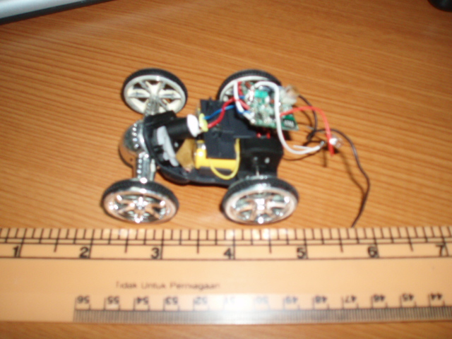
I just bought a Micro RC car for about RM20.00 (US$5).
I·want to use the·remote control·to control my Boe Bot.
Basicly the car can go forward, backward,left and right.
It use 2 rechargable battery and can be recharge by connecting the power suply from
the remote.
From the circuit there's two wire to the·front-back motor.
and two wire to left-right motor.
My question·are:
1. How am i going to connect the circuit to the BS2?
2. I want to use VDD to powr up the circuit but as i know the VDD from BS2 supply
5V. How to reduce it to 3V.
As i know how to connect the circuit to the BS i will continue with the programming.
Please help.
(Photo Attached)
640 x 480 - 153K

640 x 480 - 151K
Comments
- if you need to power that board at 3v there are lots of cheap regulators (Jameco, Digikey, Mouser, Parallax) that you can use. Hook the 3-3.3v regulator up to your Boe-bot Vin (direct battery power) and the output of that to the +3v power on the board. Connect the ground of the board to the Boe-bot ground
- it looks like there are couple of surface mount transistors driving the motor(s). Maybe it's like a simple H-bridge. The best bet would be to trace the motor output through the circuit backwards to before the drive transistors and check the input to the drive portion of the circuit with a scope and see what the signal is (current, voltage, pulse, hi/low, etc). You could tie pin(s) of the Stamp to there (through resistors to protect your pins). Depending on what kind of signal the micro board generates from remote control transmitter, you could get the info with RCTIME (e.g. if analog voltage), with PULSIN (e.g. if pulses), with pin status (if simple on/off).
- I would also think that you could check voltage and current from the motor leads, and then wire a circuit to step the current down and the voltage down/up to match the Stamp. You'd have to be careful, though, because the raw output to drive a DC motor would surely fry a Stamp pin.
▔▔▔▔▔▔▔▔▔▔▔▔▔▔▔▔▔▔▔▔▔▔▔▔
When the going gets weird, the weird turn pro. -- HST
2. A voltage regulator chip can be used to reduce the voltage to the board but you will have to know the current requirements. Is there a seperate connection for the power to the motor or is the 3V supplying both the board and motor.
I have not worked with the boe bot but but if it uses 1.5V batteries you may be able to tap off of two of them to run the board, or add a dual 1.5V AA battary pack for a 3V supply to just run the board.
Let us know what the output to the motor and the steering is.
▔▔▔▔▔▔▔▔▔▔▔▔▔▔▔▔▔▔▔▔▔▔▔▔
Think outside the BOX!
http://forums.parallax.com/showthread.php?p=555731
▔▔▔▔▔▔▔▔▔▔▔▔▔▔▔▔▔▔▔▔▔▔▔▔
Chris Savage
Parallax Tech Support
Thanks to everyone who have replied.
Chris is right this is something similar with the··Zip-Zaps BOE-Bot control in the Completed Projects Forum
but the circuit is different. After checking the output to the motor with the multimeter it read 2.8V.
It's like normal on/off switch to make the car go forward/backward and left/right.
My question:
1. Can I connect the output wire direct to the BS2 pin as input or I have to reduce the voltage first.
2. What is the maximum voltage that BS2 pin can handle.
I am planning to assingn Pin 3 for forward input Pin 4 for backward input, Pin 5 for Right input
and Pin 6 for Left input. But for now I will wait for your reply. I dont want to fry my BS2 pin.
For the power supply i will use the··voltage regulator.
Thanks a lot everybody.
- 2.8v will probably give you a "high" state on an input pin, technically speaking, but TTL is ideally 0v for low and 5v for high
- the current from the board would probably fry a Stamp pin (if it can drive a motor). But check the current with a meter -- the Stamp pin current limits are in the documentation. Others at the forums have often made the point that you should always protect a Stamp pin (with a resistor) if that pin is hooked up to a circuit that outputs voltage/current
Others may have more specific suggestions for conditioning the output of your RC board.
▔▔▔▔▔▔▔▔▔▔▔▔▔▔▔▔▔▔▔▔▔▔▔▔
When the going gets weird, the weird turn pro. -- HST
"- 2.8v will probably give you a "high" state on an input pin, technically speaking, but TTL is ideally 0v for low and 5v for high"
·- The BASIC Stamp's logic threshold is approximately 1.4 volts, so this means that it will see 2.8V as a logic HIGH.
·
"the current from the board would probably fry a Stamp pin..."
-In the event that the Stamp is made an output and the state of that output disagrees
·with what you are externally trying to "drive" that pin, then you have a potential short.
·
·For example:
·If you provided 2.8V to the I/O pin and the stamp was trying to make it an OUTPUT LOW, then
·you would have a short.· Likewise if you provided 0V to the I/O while the Stamp was trying
·to make it an OUTPUT HIGH, again you would have a short.
·
·The current limits of the Stamp I/O pins are about 20mA, so to prevent this short circuit
·situation from happening, you need to use at least a 220 Ω series resistor to limit the
·short circuit current to 5V ÷ 220 Ω = 23 mA and protect the BASIC Stamp from damage.
·
·
·
·
·Also, it's hard to determine what the Micro RC car circuit characteristics are.· In my
·experience, I have come across circuit designs (specifically servo motor drive) that
·expect there to be a "motor" on the other end.· If this is the case with the Micro RC
·car or not, I don't know.
·
·
·The link below might help...
·http://forums.parallax.com/showthread.php?p=525862
·
·Notice the resistors in place of where the servo motor once was for the modifications.· This is to "fool" the servo
or motor circuit into thinking that there is a motor connected.
·
·Direct connection approach:
·http://forums.parallax.com/attachment.php?attachmentid=37087
·
·Opto-Isolator approach:
·http://forums.parallax.com/attachment.php?attachmentid=37088
▔▔▔▔▔▔▔▔▔▔▔▔▔▔▔▔▔▔▔▔▔▔▔▔
Beau Schwabe
IC Layout Engineer
Parallax, Inc.
But there has to be something more than on / off because you have forward,backwards, left, right and straight ahead.
Is it a DC motor where the voltage reverses polarity? for forward and backwards
If it is a dc motor with reversing polarity, you could use the resistor as a dummy load as suggested and tie the two ends with two more resistors going to a simple comparator. The output on the comparator would go from high to low depending on the polarity of the voltage going to the dummy load, that output can be tied to the basic stamp pin (use another 220 ohm resistor as well just incase you do have a short in the circuit at some point)
How is left and right controlled?
▔▔▔▔▔▔▔▔▔▔▔▔▔▔▔▔▔▔▔▔▔▔▔▔
Think outside the BOX!
Thanks Beau and Metron9 for your reply.
The left and right control also the same as forward and backward.
I will try to use the 220 ohm resistor and will give you the feedback by Monday.
Thanks for help.
If so, you should check out the post Chris suggested earlier (here it is): http://forums.parallax.com/showthread.php?p=555731.
I am pretty sure that these electronics wont be affected by the lack of a motor present, I believe they are just simple transistors that turn on and off when given signal from the remote. You should be able to connect it directly (with 220 resistors for protection), however it may be possible that their is electrical interference between the RC unit and its circuits and whatever else you have connected to your stamp. If that happens, you could use a comparator IC as metron9 suggested (you can get them at radioshack), or if it still doesn't work, you could completely isolate the two with an opto-isolator IC, although at this point, I don't think it would be worth the trouble to get the remote control working, since you could probably find a better remote (more buttons, proportional) that is easier to get working.
Sorry for late reply. Got job to do.
Anyway I manage to make the car go forward and backward without using the 220 ohm resistor.
If i put the resistor the car won't move maybe because of the low voltage.
The problem now· it can't go left and right.
Here I attached the code.
Anyone can help?
Thank you.