Robotics - Servo controlled Arm design
Hi,
I am designing a robot arm and wanted some expert opinion on mechanical design considerations. Here is what I am looking for:
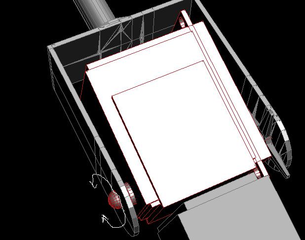
I am enclosing one of the servos in an aluminum casing as shown in the attached autocad photo. The moving part is a U shape aluminum part - one arm of which is connected to the servo horn. The servo drives this U part. However, since I cannot leave the other arm of the U shape hanging - it has to be riveted to the back of the servo, such that the rivet is along the axis of the servo shaft.
The entire U shape swivels around with respect to the servo.
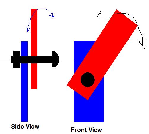
What is the best method of riveting this part to the servo? I have also attached a simple drawing to simplify the question. Its a badly made paint brush job [noparse]:([/noparse]
Anyways, there is the stationary aluminum plate (part of the U shape aluminum frame) shown in BLUE. And the moving aluminum plate which is rotating around the servo is RED. The axis of rotation is shown in BLACK.
Whats the best design for this mechanical part? I am using ALUMINUM PARTS only.
I appreciate all the help. Thanks folks.
▔▔▔▔▔▔▔▔▔▔▔▔▔▔▔▔▔▔▔▔▔▔▔▔
E=mc^2


Comments
▔▔▔▔▔▔▔▔▔▔▔▔▔▔▔▔▔▔▔▔▔▔▔▔
When the going gets weird, the weird turn pro. -- HST
kelvin
I will post the pics of my robot arm once i build it (perhaps in a week or 2).
I would appreciate any more suggestions or comments.
Thanks all.
aaqil
▔▔▔▔▔▔▔▔▔▔▔▔▔▔▔▔▔▔▔▔▔▔▔▔
E=mc^2