

Old car dashboard displays, can they be used for projects?
 metron9
Posts: 1,100
metron9
Posts: 1,100
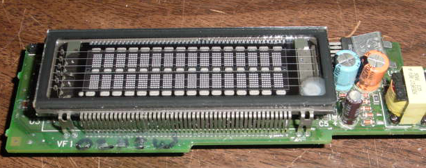
The guy I helped out with the issue on that dashboard has tons of these displays. When I had a working board I did not take any voltage measurments of the working display. Does anyone know what voltage something like this takes AC or DC. I am thinking of pulling just the display and trying to light individual dots on the display, If I knew what voltage was needed I could figure out what wires to connect (eventually) and make some nice displays.
▔▔▔▔▔▔▔▔▔▔▔▔▔▔▔▔▔▔▔▔▔▔▔▔
Think outside the BOX!
▔▔▔▔▔▔▔▔▔▔▔▔▔▔▔▔▔▔▔▔▔▔▔▔
Think outside the BOX!
612 x 242 - 167K
Comments
(That black thingie at the top right corner of the picture)
What is it marked with?
Are there any ICs on the board?
▔▔▔▔▔▔▔▔▔▔▔▔▔▔▔▔▔▔▔▔▔▔▔▔
Don't visit my new website...
15277   5151-2
           MAL
16246628
  9929J
Thats what it is marked with, I get the usual stupid "part miner" links with no clue about even what the device is.
I think the board generates higher voltage though because of the transformer and the coil at the far right.
I will get a working unit again next week if I have time and poke around with a probe. I will also find out how many of these things he has because they could make some very nice displays for projects, they are made of three layers of glass, I wish i could find some kind of datasheets for the same type device.
▔▔▔▔▔▔▔▔▔▔▔▔▔▔▔▔▔▔▔▔▔▔▔▔
Think outside the BOX!
Now comes the fun part the to controll the Control grids (the fine mesh over the little dots) & the Illumination Anodes (the little dots that form the 5x7 matrix). both the grid & the Anodes must have a positive voltage (12V to 35V should be a good starting point). now a 9V battery might help you find out what pin do what but it will not be bright. take the AA batteries that you used befor, hook them to the filament, then take the negative side of the 9V battery and hook it to the negative side of the AA battery hooked to the filament. now take the positive side of the 9V battery (with some wire, with the end striped off) and run the wire down the pins ( the ones close together, DO NOT TOUCH THE FILAMENT PINS!!!!). it will take some time to find out what pins do what. after time you should see that, each grid controls each 5x7 matrix under it. but every 5x7 matrix on the top row are hooked together, and every 5x7 matrix on the bottem row·are hooked together.
It is very hard to explain how to work with VFD displays like this, but once you understand how to work with them it gets real easy.
here are some sites that might help you understand how they work,
http://www.noritake-elec.com/vfd_technology.htm#1VFDOP
http://www.allegromicro.com/techpub2/futaba/appnotes.htm
I do hope this helps.
TC
▔▔▔▔▔▔▔▔▔▔▔▔▔▔▔▔▔▔▔▔▔▔▔▔
We all make mistakes when we are young………That’s why paste is edible!
Pins from 1-16 on bottom and 17-32 on top, here is the data to light the display.
I used about 2V DC, I have a 5 ohm resistor as well while testing to slow the current down a bit,
the heater measues 4 ohms
So two pins on the bottom row, pins 3 and 4 control two banks of 3 digits
Three cascaded shift registers would be able to drive the 6 digits.
Measuring the current, each segment takes .1 mA, the TRIP takes 1mA at 9V
Interesting how the current is greater when the heater is fed a higher voltage.
The heater takes 100mA at 2V, thats with the 5ohm resistor in series. I have read about pulsing the heater as well.
I guess the AC would extend the life of the filament (heater)
Is it because it would only be a 50% duty cycle and run cooler
but your eye would see the same brightness. It also allows higher voltage
to drive the filament at the same temperature so the display would
appear brighter to the human eye.
TRIP 3,30
DEC 4,30
▔▔▔▔▔▔▔▔▔▔▔▔▔▔▔▔▔▔▔▔▔▔▔▔
Think outside the BOX!