

Solution to 1989 Olds Toronado Instrument Panel <<<ALMOST SOLVED>>>>
 metron9
Posts: 1,100
metron9
Posts: 1,100
New information below this original block of text
I pretty much think I solved the problem because I can't make it not work anymore. I guess having a scope really pays off, I will give the secret to my buddy that fixes gauges for a living. The problem was intermittant power reset comming from the power supply circuit. Most of the stuff I found online even from the manufacture had the solution wrong (well 1/2 right but it never actually fixed the problem).
Time will tell but I have a dashboard running for 6 hours now with dozens of power ups and downs and it just keeps on working like it should. I reinstall the factory circuit specs and it malfunctions randomly.
Is there anyone here that fixes old circuit boards that malfunctuions randomly, are there specifiic components that typically simply wear out from age that cause most of the problems or is it bad circuit design in the first place?
Think I will have a beer now but as always I will look for more difficult problems to solve when I again get board with all the other non electronic stuff.
I need hard problems (with simple solutions) that just seem complicated.
<<<<<<<<<<< New information >>>>>>>>>>>>.
The board I worked on where I simply reduced the size of the capacitor won't malfunction, the same soultion for another board is NOT WORKING.
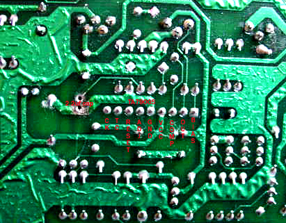
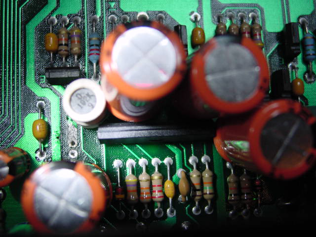
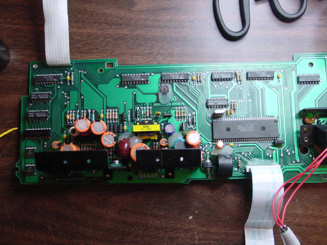
I have attached two pictures, front and back of board. I would like the help of you folks to try and diagnose this problem.
I can make it work but I don't think adding a reset button will be what people want so I need to make an automatic reset circuit.
Here is what happens. When the board is powered up it sometimes fails to come up. I believe it is because the voltage regulator not sending a reset signal for some reason. The small capacitor when desoldered and resoldered into place makes the board come up at least the first time without fail, thereafter it fails to come up. It is connected to ground and to a resistor that goes to pin 6 on the TA7900S. In some of the forums on the net it is said the capacitor failed and replacing the cap with a new one fixes the problem, it use too, the boards are getting older and something must be going bad on the board, perhaps the crystal that runs the processor is not starting fast enough at powerup or who knows but speculate anyhow what do you think?
What works to bring it up:
I removed the capacitor, power up, and then just touch the point on the board where the one side of the capacitor ties into a resistor that goes to pin 6 of the TA7900S with 12V through a 10K resistor. This lowers the output voltage as the datasheet shows, and must generate a reset signal when I remove the power from that point. The board is now running. If I touch the point again and hold it the board turns off, removing it again the board comes back on.
Please look at the datasheet on the TA7900S and the photos and see if you can come up with a combination of components that will at powerup apply the voltage I am doing manually.
I will also look at the watchdog part of this regulator, I think adding a bigger capacitor for the startup delay could also work.
Please toss in any ideas you may have that could perhaps lead to a solution.
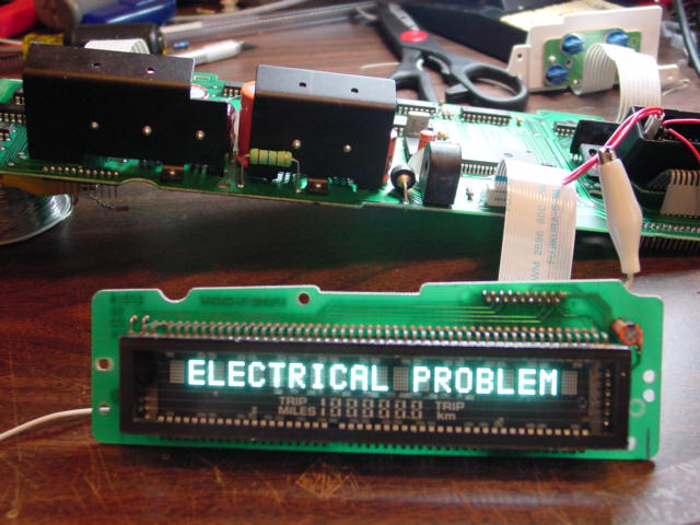
The display picture says "ELECRTICAL PROBLEM" this message is true but when it says that it means it is working, the rest of the gauges are not attached so it is not getting feedback from them, that's all. It is the actual booting up of the device, power to the regulators that will not happen unless I manually reset the main power regulator by the above mentioned procedure.
One more thing, I just hooked up a short wire to that same spot where the capacitor was, I put my voltage multimeter on it to read the voltage it has what it needs to make it work. The ground pin hole is unconnected but simply putting the volt meter on the other side gives it what it needs so there must be a way to put something in that spot that will do the same thing perhaps a nanofarad capacitor.
▔▔▔▔▔▔▔▔▔▔▔▔▔▔▔▔▔▔▔▔▔▔▔▔
Think outside the BOX!
Post Edited (metron9) : 9/28/2006 10:12:47 PM GMT
I pretty much think I solved the problem because I can't make it not work anymore. I guess having a scope really pays off, I will give the secret to my buddy that fixes gauges for a living. The problem was intermittant power reset comming from the power supply circuit. Most of the stuff I found online even from the manufacture had the solution wrong (well 1/2 right but it never actually fixed the problem).
Time will tell but I have a dashboard running for 6 hours now with dozens of power ups and downs and it just keeps on working like it should. I reinstall the factory circuit specs and it malfunctions randomly.
Is there anyone here that fixes old circuit boards that malfunctuions randomly, are there specifiic components that typically simply wear out from age that cause most of the problems or is it bad circuit design in the first place?
Think I will have a beer now but as always I will look for more difficult problems to solve when I again get board with all the other non electronic stuff.
I need hard problems (with simple solutions) that just seem complicated.
<<<<<<<<<<< New information >>>>>>>>>>>>.
The board I worked on where I simply reduced the size of the capacitor won't malfunction, the same soultion for another board is NOT WORKING.
I have attached two pictures, front and back of board. I would like the help of you folks to try and diagnose this problem.
I can make it work but I don't think adding a reset button will be what people want so I need to make an automatic reset circuit.
Here is what happens. When the board is powered up it sometimes fails to come up. I believe it is because the voltage regulator not sending a reset signal for some reason. The small capacitor when desoldered and resoldered into place makes the board come up at least the first time without fail, thereafter it fails to come up. It is connected to ground and to a resistor that goes to pin 6 on the TA7900S. In some of the forums on the net it is said the capacitor failed and replacing the cap with a new one fixes the problem, it use too, the boards are getting older and something must be going bad on the board, perhaps the crystal that runs the processor is not starting fast enough at powerup or who knows but speculate anyhow what do you think?
What works to bring it up:
I removed the capacitor, power up, and then just touch the point on the board where the one side of the capacitor ties into a resistor that goes to pin 6 of the TA7900S with 12V through a 10K resistor. This lowers the output voltage as the datasheet shows, and must generate a reset signal when I remove the power from that point. The board is now running. If I touch the point again and hold it the board turns off, removing it again the board comes back on.
Please look at the datasheet on the TA7900S and the photos and see if you can come up with a combination of components that will at powerup apply the voltage I am doing manually.
I will also look at the watchdog part of this regulator, I think adding a bigger capacitor for the startup delay could also work.
Please toss in any ideas you may have that could perhaps lead to a solution.
The display picture says "ELECRTICAL PROBLEM" this message is true but when it says that it means it is working, the rest of the gauges are not attached so it is not getting feedback from them, that's all. It is the actual booting up of the device, power to the regulators that will not happen unless I manually reset the main power regulator by the above mentioned procedure.
One more thing, I just hooked up a short wire to that same spot where the capacitor was, I put my voltage multimeter on it to read the voltage it has what it needs to make it work. The ground pin hole is unconnected but simply putting the volt meter on the other side gives it what it needs so there must be a way to put something in that spot that will do the same thing perhaps a nanofarad capacitor.
▔▔▔▔▔▔▔▔▔▔▔▔▔▔▔▔▔▔▔▔▔▔▔▔
Think outside the BOX!
Post Edited (metron9) : 9/28/2006 10:12:47 PM GMT

Comments
Draw out (or locate) a schematic of the board, and use the scope to trace the signal.
If you're not too certain of what to look for on a particular component, put the good maodule in and see what you get at the same points. Then when you find the bad signal, you'll know it.
I guess the story went like this. These panels failed in many cars because of a 2.2uf capacitor that blew and was smack flush on the board so it shorted the pads and messed up other components it is said. The gauge guy would pull the 2.2uf cap replace it and then it worked fine, but that was in years past, now the boards are comming back and the capacitor is not blown but just solder in a new one (or desolder and resolder the old one) and it works... for a while intermittantly not booting up after running for a while.
So I soldered in a jumper wire so I could just test the capacitor when it stopped working again (stopped working i.e. turn off power and power back up.) the story goes the panel would sometimes take 5 min or more to come up getting longer and longer times and then just not working. Back to my jumpers, when it did not work anymore I unclipped the cap, the scope was still connected across the jumpers and what the heck it started working again like an open fet gate where you touch it just right and it triggers the gate. Not consistant boots but better than when the 2.2uf cap was in place.
So I said Hmmm there must be stray capacitance and it must be much smaller than 2.2uf, that being the case I tried a 0.10uf and no go, so I tried a 1000PF, it started working and I can not make it malfunction anymore. So I solved it, as this board was in the trash heap because they could not get it to work without failing many times. He showed me this for about an hour today so I took the board home just to play with it. I guess repair is said to be $180 bucks or so so I think I will ask for a few bucks for each one he fixes down the line.
▔▔▔▔▔▔▔▔▔▔▔▔▔▔▔▔▔▔▔▔▔▔▔▔
Think outside the BOX!
The key thing is to make more notes then you think you are ever going to need. For me it was the small details that provided the clue.
As far as 'suspect components that fail more often than others'....that's a general question and the general answer may not give you what you want.
When troubleshooting, I usually do the visual....anything black or discoloured? If there is, I then follow the traces out from there to see if something else was affected.
The other places I start is at the 'real world' connection points. So wherever a wire leads from the board to some other component it connects to. Sometimes, the front end or back end might be blown as something from the outside world got on to your wire and your board didn't like it.
In general, I'll check diodes for opens or short (diodes should typically have infinite resistance one direction and 'some' resistance in the other direction/polarity); caps, measure resistance and see if it changes as you hold it there, flip the leads around and watch the resistance change again.
I hate leaky capacitors....I don't have a cap checker onmy meter and suffer through guesses
Transistors (NPN/PNP) I usually check for shorts between the base and emitter....
Cheers
Note: you'll have to remove at least one leg of a component to test it properly.
Some of those old boards weren't all that complex....tracing it only takes time and patience.
▔▔▔▔▔▔▔▔▔▔▔▔▔▔▔▔▔▔▔▔▔▔▔▔
·
Steve
"Inside each and every one of us is our one, true authentic swing. Something we was born with. Something that's ours and ours alone. Something that can't be learned... something that's got to be remembered."
Remembering how pullups work when I learned about I2C, I hooked up a 100k resistor to ground and the other side to where the capacitor leg was on the board, I also connected a capacitor from VCC to the same point. When the power is turned on the initial power comming through the capacitor puts voltage on the ADJ pin 6 of the regulator, when the capacitor is full the voltage drops back to ground through the 100k resistor, the voltage regulator then resets the system and all is well....
I have 1 1000UF capacitor
20K resistor---->GND
.......................................||>>> to regulator pin 6 ADJ
This gives a 3V surge when the power is applied to the board, and drops back to about .5V
I will have to do some math to reduce the capacitor size with a bigger resistor, not sure how much current it will take but I dont think it's much.
Could well be solved now...
more testing before I know if it's a solution.
▔▔▔▔▔▔▔▔▔▔▔▔▔▔▔▔▔▔▔▔▔▔▔▔
Think outside the BOX!