

MOSFET H bridges?
 tperkins
Posts: 98
tperkins
Posts: 98
Anyone homebrewed a big inverter?
All other projects are on hold until I build or get disgusted with a whole house inverter--I've moved to a location that loses power about once a week--half a second, half a day, whatever.
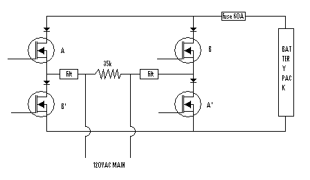
I'm looking at using the STY60NK30Z MOSFET in an H-bridge to PWM a sine wave 120VAC RMS voltage at 5+kHz sine wave into a 60Hz bandpass filter to produce mains type power, chopping the DC from a 254VDC nominal battery bank. So far I've gotten "rectified" sine waves with a single transistor doing the switching at 500Hz into a purely resistive 240 V nominal load (two light bulbs in series). The half sine waves look good on a scope.
Everything I've done with MOSFETs so far has been small signal DC stuff.
But to make actual AC with these MOSFETs (ultimately 3 H-bridges for a total of 12 of them, each bridge triggering in turn for each third AC cycle) instead of a BJT, I think a first look at it will look like the attachment below.
I feel okay working with mains and high amps, I occaisionally do that at work (had to travel to repair a 500A 480V SCR stack 5 months ago, for example).
Any pointers?
Thanks Tom Perkins
All other projects are on hold until I build or get disgusted with a whole house inverter--I've moved to a location that loses power about once a week--half a second, half a day, whatever.
I'm looking at using the STY60NK30Z MOSFET in an H-bridge to PWM a sine wave 120VAC RMS voltage at 5+kHz sine wave into a 60Hz bandpass filter to produce mains type power, chopping the DC from a 254VDC nominal battery bank. So far I've gotten "rectified" sine waves with a single transistor doing the switching at 500Hz into a purely resistive 240 V nominal load (two light bulbs in series). The half sine waves look good on a scope.
Everything I've done with MOSFETs so far has been small signal DC stuff.
But to make actual AC with these MOSFETs (ultimately 3 H-bridges for a total of 12 of them, each bridge triggering in turn for each third AC cycle) instead of a BJT, I think a first look at it will look like the attachment below.
I feel okay working with mains and high amps, I occaisionally do that at work (had to travel to repair a 500A 480V SCR stack 5 months ago, for example).
Any pointers?
Thanks Tom Perkins
bmp
343K
Comments
You don't say how big a unit you need, but unless you really want to spend the time learning about big inverters, just purchase a standard marine unit, say 3KW or 5KW which converts 12 or 24 volts DC into 120/240 AC. Not perfect sine wave power, but you're probably feeding switchmode power supplies anyway (electronics, computers, etc) so there's no real problem.
Set up a couple of deep cycle batteries with a properly sized charger and feed the inverter.
If you need 3 phase power, get yourself an industrial variable frequency motor drive. Feed the DC bus on the drive with your 254volt battery bank and gnererate 3 phase power at will.
Cheers
▔▔▔▔▔▔▔▔▔▔▔▔▔▔▔▔▔▔▔▔▔▔▔▔
Tom Sisk
http://www.siskconsult.com
·
Trace Engineering makes some very nice inverters (multi-KW) for the solar market that will fit the bill, and are legal to intertie with your existing house wiring. If all you want to power is something small, there are lots of off the shelf units that perform admirably.
The legal and code issues of tying it into your mains system are beyond the scope of this forum, but having dealt with them once, I'd never ever want to try and install a handmade inverter in my house.
That said, if all you need to power is something small like a few light bulbs or a fan, there are lots of ways of making it work. What is the real VA/W requirement you're looking for?
-dave
▔▔▔▔▔▔▔▔▔▔▔▔▔▔▔▔▔▔▔▔▔▔▔▔
This is not a sig. This is a duck. Quack.
I appreciate the relatively discouraging words. I do know they are well intentioned. FYI, the system would not be attached to the grid. Ever.
Dave, would you agree that something like the "forced commutation" or "gating" used in high end SCRs is also required to switch fully loaded MOSFETs or IGBTs at freqs in the neighborhood of 10kHz +/- 5kHz? Also, while the MOSFETs would only occaisionally see up to their maximum amp current flows seen as RMS values, they would commonly see repetitive peaks which are about %80 of the overall maximum. I'm looking at this as 3 bridges triggered each for one AC cycle, and then the next bridge makes a cycle, and then the next a cycle, and then the first bridge makes another cycle, etc. Is the sole issue resistive heating of the die and gate? The "safe operating area" of the STY60NK30Z would appear to limit I max RMS for the inverter overall to 180A (permitting 180A service at 120VAC RMS)--but the highest voltage I could chop would be about 215VDC, only allowing the (currently 20, in this case 16) batteries to be drained to about 11.1VDC each before 100% duty cycle won't produce a 167VACmax for 120VAC RMS.
So I'm looking also at the STGE200NB60S IGBT. But it has a max freq of 1kHz, which is low, and I haven't found how the VCES and IC affect the Fmax. It should make 150A AC with a single bridge.
And I know where to salvage a transformer core from to provide filtering, provided I can get it out of the ground. The are no oil issues with it either and it's big enough it will never saturate.
Also, I am not anticipating any power transformers. I would instead PWM 254VDC* onto the load, with the PWM accomplishing a 120VAC RMS sine wave after filtering. A sine wave with 3% or less THD is the goal.
*I've bought 20 of 5Ah batteries for developing the circuitry, that's what's sourcing the power transistor for the rectified sine wave my single BUX348 is producing. I may test the overall concept with three more of these for an H-bridge. For the final app. I need 20 batteries that supply around 175Ah at the voltage the chopper can survive while the batteries are still at an acceptable level of charge--permitting them to last around 10-20years. They would be in a shirtsleeve environment.
The eventual goal is to develop a 150A (+/-50A) 120V 60Hz inverter and go off grid. The missus' requirement is that she shouldn't be able to tell the difference between the power company and what i'm doing. I sympathize. I may have a use for the waste heat from the powerplant, which is good 'cause the power company charges me $21.00 for the power I could conceivably generate with $48.00 dollars of wood pellets. Overall conversion of fuel to elec power I think will be 28% eff. Conversion is going the wood gassifier>IC engine>DC electric>AC electric route, so fuel costs drop by 50 to 75% if I figure out how to gassify stovewood. Big incentive to figure that out.
And with the way information has so far been hard to find, write a book about it. ;^)
I'm thinking the Propellor as a more than adequate mcu for both the app., monitoring, and user interface.
Thank you, Tom Perkins
Post Edited (tperkins) : 9/27/2006 5:42:05 PM GMT
If You're going to dream, you might as well dream in Technicolor!
Back in the '80's I was involved with such projects. The gassifier to electric route will be quite a bit less than 28% efficient. Even a new diesel engine can hardly deliver that in fuel to mechanical power, let alone to electric.
Have fun!
▔▔▔▔▔▔▔▔▔▔▔▔▔▔▔▔▔▔▔▔▔▔▔▔
Tom Sisk
http://www.siskconsult.com
·
The trick with good gassifier efficiency is to keep the char bed at at least 850degC and the gas velocity at around 22fps or lower at exit (when velocity should be at a maximum) and then chill the fuel gasses to near ambient as quickly as possible before the CO can break down into soot and C02. As long as you keep the char bed at that 850degC while adding as much water vapor as you can while doing it, the hot char will strip it into CO and H2. Keeping the H2 % high lets you use very high compression ratios in the IC engine. Recirc some fuel gas to a burner in the upstream portion of the fuel stack so you burn off the volatiles as quickly as possible, so there is as much time for the charcoal to react with the gasses as possible. Insulate heavily, because this isn't a mobile plant, and use reverse flow heat exchangers or Lungstrom regenerators to conserve heat. 85% percent conversion of wood BTUs to fuel gas BTUs is not hard.
Stationary diesels regularly achieve 35% efficiency.
Where are the issues there?
More to the point, I haven't found IGBT or MOSFET gating circuit design tools online yet.
Can you help there?
Thank you, Tom Perkins
Post Edited (tperkins) : 9/27/2006 8:38:20 PM GMT
Yours, Tom Perkins
In all honesty, with the time and effort you're going to spend building a 150Ax120V inverter (18KW nominal) you can find an array of used ones and install them, with a greater safety factor than something you'll build yourself. I wirtte discouraging words primarially because of the immense difficulty of building a system that can safely PWM 150A of 120VAC, all the time, with the reliability you'll require, with the load dump durability you'll need when your fridge, air conditioner, and hairdryer all turn on or off at the same time, not to mention putting all of the parts together into a system that will be safe and durable for the forseeable future. The management features on modern inverters are worth the price all by themselves in my opinion. Seriously...do a cost benefit analysis, count your time as money.
That said...
A 10KHz switching frequency is one that will work for you, but I'd highly recommend using a TON of smaller devices, rather than a few large ones. Smaller devices are easier to buy, easier to heatsink, distribute the load over more points (reducing the impact of a single point faulure), and are, most importantly, FASTER. The IRFB260N is one I've used very successfully before. Yes, it's SOA limited to a few amps at 120VAC, but it's cheap and has a crazy low Rdson. The IRFP360LC is my choice for larger units, where heat is more easily managed..bigger SOA, not quite as fast, but good enough. Using a number of FET drivers (the UCC37322 is one I like) can simplify the drive process as well. 6-10oz copper and a 6 layer PCB is in your best interest for final construction (double up the layers). If you float the ground on the drive board and use an opto to feed your PWM signal to the drivers, you have no need for high voltage drivers...just use the N channel FETs back to back and make the common sources 'ground' and build a high side switch out of the deal. Make sure your transformer/choke assembly is up to the task of the load transients you'll have. I'm serious about the fridge/AC/hairdryer situation. That can put close to 100A of startup load on your system in an instant. I'd overdesign for peaks of 200-300% of the intended constant load. Don't use welding cable for interconnects...pay for the real deal (ultraflex 2/0 ought to work for you).
My real question to you though, is if you're going to commit to living off the grid, why not try and reduct your power consumption? 150A is a TON of power.
And finally...what are you goign to be doing for a charge controller for the batteries this thing will need to run off of?
-dave
▔▔▔▔▔▔▔▔▔▔▔▔▔▔▔▔▔▔▔▔▔▔▔▔
This is not a sig. This is a duck. Quack.
I haven't found any inverters in any where near that power rating, short of a UPS for server farms doing 24kw going for about $28k.
I actually expect the system I'd like to build to average about 7A at 120VAC, rarely peaking past 70A, the 150A IS a safety factor all by itself.
WRT to loads suddenly increasing or decreasing, I was under the impression that PWM DC into the filter largely took care of that, because there would be no large quantities of energy stored in a step up transformer core. I thought that power lead and filter stored energy could be handled by diodes and (as a sacrificial component) MOVs. Also I planned on cutting out some low priority loads like the HVAC and water heater whenever the amperage got much past 50 or so (and replacing the electric water heater as soon as I could, since I need to shoehorn a water softener into the cellar soon anyway, to do that the water heater got to be moved, may as well move it far).
I was skeptical of acceptably even sharing using devices in parallel to increase amperage.
Certainly another alternative, given the lower BTUs/ft^3 gas that a gassifier generates, buying a 40kW diesel genset and derating it by half is an option. But from what I know now, it would by far be a more expensive option. As I find sources, I may well know differently later.
I'm still digesting the second half of your last post, but the plan for charging was five 48V truck alternators cap filtered and seriesed up. That hadn't been as closely examined as the rest of it, because I'd orginally thought of just using single car alternator and cutting in either of two banks for charging to 14 or so volts.
Yours, TDP
Post Edited (tperkins) : 9/27/2006 11:37:41 PM GMT
No problem, just 2 guys talking about big power here
If you're only looking for 7-60A, then your options increase radically. From what you wrote, I think a 70-80A system would be just fine for you. A gas water heater and a gas clothes dryer would be helpful to that end, as those are two of the biggest electrical loads in any house. I bet with some agressive power management you could get down to 20-30A, and get yourself one or two (used examples) of the commercial inverters/chargers/window-washers/shoe-tiers and a stacking kit for a more reasonable sum of money.
For the under 50A set, a well tuned diesel genset with a sinewave stabilized generator and a big tank of B100 biodiesel sounds like a good way to go to me.
Large numbers of devices will share the current happily. FETs are negative tempco devices, so as they take more, they heat up, take less, and self-equalize. If you feel the need, a 0.01R resistor on each drain will make sure. So far I've scaled the common source pair scheme to about 100 devices, good for something in the neighborhood of 175A (thermally limited by the PCB, not the FETs). There's some fear when you plug something like that in for the first time, but it does work. Just keep them cool and make sure they're all bolted to the same chunk of aluminum so the heat is shared.
Charging is that will make or break a battery system. I'd look hard into the systems used commercially, where longevity and performance are the norm.
-dave
▔▔▔▔▔▔▔▔▔▔▔▔▔▔▔▔▔▔▔▔▔▔▔▔
This is not a sig. This is a duck. Quack.