

Need PCB advice
 PVJohn
Posts: 60
PVJohn
Posts: 60
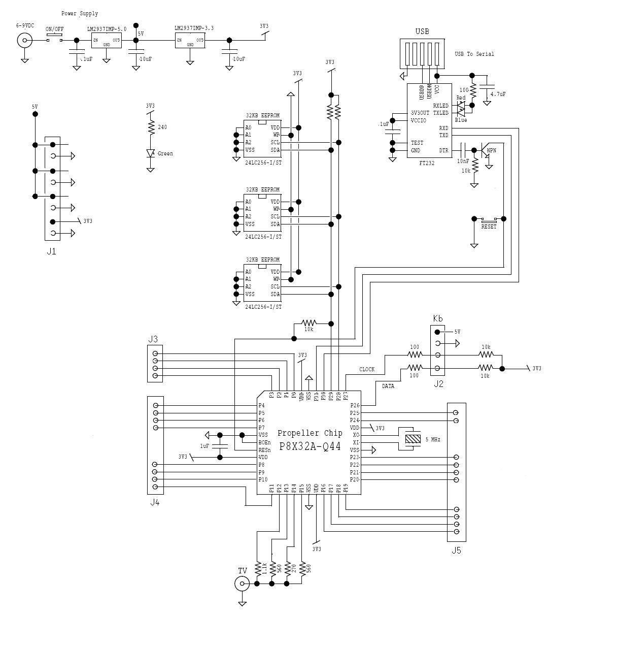
I would like to make my first PCB with SMD components, but before I do that, wanted to ask an expert(s) if this is going to work or not. I'm not sure which FT232 chip to use since I'll solder it by hand. Is there any example how to read/write to additional EEPROMs?
Thanks,
PVJohn
Thanks,
PVJohn
1216 x 1272 - 103K
Comments
First thing that came to me was that I would parallel the regulators off the source rather than have the 5V regulator bear the loads of 5V AND 3.3V...
As to the +5V regulator cascading into the 3.3V one there is nothing wrong with doing this in this application. The +5V rail is only ever really powering the keyboard and maybe some light external loads. There is no real load on·the +5V·plus it helps to spread the power/heat dissipation across two regulators.
As the I2C bus is only ever a single master you can omit the pullup for the clock line. You have a resistor going from SDA to reset, a drafting error perhaps? The reset line does not need a pullup as it the BOE line is pulled low and this makes the reset line a weak output/input with internal 5K pullup.
Observe good PCB layout especially for crystal and ground and power-supply decoupling.
As an option it can be a good thing to have a status led and you could make good use of the SCL line if you did not have any others available.
Remember too that if you want good·A/D conversion using sigma-delta that you should have components mounted as·close as possible to the chip, inside if that were possible.
*Peter*
·
Hope this helps
Mark
Mark, thanks for your files.
Regards,
PVJohn
Oh and you shouldn't pull the i2c lines using the reset line, as this prevents the chip doing a controlled reboot.· Best practice is to pull both SDA and SCL lines to +3.3v via a 4.7K resistor - this is documented in the i2cObject referenced above.
James