

Propeller Object: Hitachi H48C Tri-Axis Accelerometer Module
 Beau Schwabe
Posts: 6,576
Beau Schwabe
Posts: 6,576
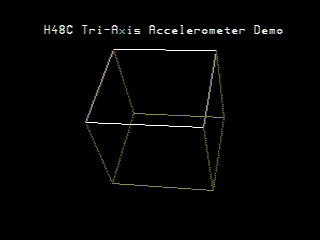
Here is a DEMO object using the Hitachi H48C Tri-Axis Accelerometer Module.
The 3D graphics engine still needs a little work, but all in good time.
This might actually work well with a compass module also.

▔▔▔▔▔▔▔▔▔▔▔▔▔▔▔▔▔▔▔▔▔▔▔▔
Beau Schwabe
IC Layout Engineer
Parallax, Inc.
Post Edited (Beau Schwabe (Parallax)) : 9/13/2006 10:44:26 PM GMT
The 3D graphics engine still needs a little work, but all in good time.
This might actually work well with a compass module also.
▔▔▔▔▔▔▔▔▔▔▔▔▔▔▔▔▔▔▔▔▔▔▔▔
Beau Schwabe
IC Layout Engineer
Parallax, Inc.
Post Edited (Beau Schwabe (Parallax)) : 9/13/2006 10:44:26 PM GMT
320 x 240 - 9K
zip
479K
Comments
Wow! I'll never cease to be amazed at what this PChip (and a guru programmer) can achieve
Any chance you would give me some pointers on how to achieve the same with·two MEMSIC 2125s?
▔▔▔▔▔▔▔▔▔▔▔▔▔▔▔▔▔▔▔▔▔▔▔▔
Cheers,
Simon
Post Edited (simonl) : 9/14/2006 4:51:32 PM GMT
It's really just a matter of plugging in the deg values for X,Y, and Z
With the MEMSIC 2125 your only going to have one Deg value that can be substituted into either/or/and the X,Y,Z parameters.
See this link below...
http://forums.parallax.com/showthread.php?p=605385
▔▔▔▔▔▔▔▔▔▔▔▔▔▔▔▔▔▔▔▔▔▔▔▔
Beau Schwabe
IC Layout Engineer
Parallax, Inc.
I have tried the H48C cube program that you created, but the cube is stationary on the screen. The graphics to the TV work well, I think the problem is with the accelerometer. Any ideas on how to fix it?
There should be a white dot on the PCB board (upper left) denoting pin 1 ... if you go by the dot on the chip itself (lower right) is closest to pin 3
▔▔▔▔▔▔▔▔▔▔▔▔▔▔▔▔▔▔▔▔▔▔▔▔
Beau Schwabe
IC Layout Engineer
Parallax, Inc.
I checked and rechecked the pin configuration. Still no luck. I also checked to see if it was the accelerometer itself, but it works flawlessly with a BASIC STAMP. In the DEMO program, I also tried to change the pins, making them easier to get to using jumper wires, but no luck as well. There is an output to the tv, it will display the cube, but the cube does not move when the accelerometer is moved. I also tried other accelerometer programs, mainly this one: http://forums.parallax.com/forums/attach.aspx?a=8945, which is the .sensor.hitachi.h48c.diagnostic and the accelerometer will not communicate with the prop. (I placed an LED in parallel with the clock pin, so I could visually see if the prop was communicating, but nothing)
Bryan
The ".sensor.hitachi.h48c.diagnostic" from this point (http://forums.parallax.com/showthread.php?p=602451) in the thread was not working according to 'tyrebiter'.
If you look further down, the code that 'tyrebiter' posted that works is here (http://forums.parallax.com/showthread.php?p=605174).
You are supplying the accelerometer with 5V on pin 6 of the accelerometer correct? ...and the VSS connections are shared between Prop and accelerometer right?
▔▔▔▔▔▔▔▔▔▔▔▔▔▔▔▔▔▔▔▔▔▔▔▔
Beau Schwabe
IC Layout Engineer
Parallax, Inc.
I have also tried that program. I wired an LED up to the clock pin, to see if there would be any signal, and there appears to be no clock signal going to the accelerometer. Do you have any other suggestions?
Bryan
Use a 220 Ohm resistor in series with your LED from the Propeller I/O to VSS
[b]CON[/b] [b]_CLKMODE[/b] = [b]XTAL[/b]1 + [b]PLL[/b]16X [b]_XINFREQ[/b] = 5_000_000 LEDpin = 1 <- adjust this to a different pin [b]PUB[/b] Toggle [b]dira[/b][noparse][[/noparse]LEDpin]~~ [b]repeat[/b] ![b]outa[/b][noparse][[/noparse]LEDpin] [b]waitcnt[/b](3_000_000 + [b]cnt[/b])Then try another set of pins on the Propeller and ajust your code accordingly
▔▔▔▔▔▔▔▔▔▔▔▔▔▔▔▔▔▔▔▔▔▔▔▔
Beau Schwabe
IC Layout Engineer
Parallax, Inc.