

How to connect BS2 to H-Bridge motor
 azmax100
Posts: 173
azmax100
Posts: 173
Hi all
I have problem how to connect BS2 to H-Bridge motor.
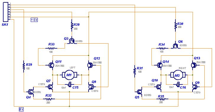
Here I attached the schematic diagram of the H-Bridge.
Pls help.
I have problem how to connect BS2 to H-Bridge motor.
Here I attached the schematic diagram of the H-Bridge.
Pls help.
728 x 378 - 40K
Comments
I'm not sure I see your problem. Here's the way I read the schematic:
Pin 7 - V-
Pin 6 - V+
Pin 5 - unconnected
Pin 4 - control lines for
Pin 3 - motor # 1
Pin 2 - control lines for
Pin 1 - motor # 2
Motor Control Pins
0 0 = motor off
0 1 = motor FWD
1 0 = motor REV
1 1 = DO NOT USE!
What's more to say?
Regards,
Bruce Bates
▔▔▔▔▔▔▔▔▔▔▔▔▔▔▔▔▔▔▔▔▔▔▔▔
<!--StartFragment -->
1) R29 and R32 seem to be swapped with each other as well as R31 and R35
2) I would remove C15 and C16 and replace them with bridge rectifiers.
For M1, connect each AC terminal "~" to the motor, then connect the "+"
to the connector pin 6 and the "-" to the connector pin 7. Do this again
for M2.
▔▔▔▔▔▔▔▔▔▔▔▔▔▔▔▔▔▔▔▔▔▔▔▔
Beau Schwabe
IC Layout Engineer
Parallax, Inc.
Thanks to·Bruce & Beau· for your reply.
Actually I'am giving wrong info. What I want to do is connecting the circuit to BOE.
How to connect SK1 to the BOE. I want to use external power supply to the circuit. not from the BOE.
Sorry for that.
For the Bridge Rectifiers can u draw the schematic diagram how to replace the C15 & C16.
I'am only beginners so i can't understand trough words.
That's what you should do anyway. What you need to do though is connect
the grounds together.
Basically you would have 2 of the circuits below. And apply the truth table
from the BOE. Select the I/O pins that you will want to use for the output.
You will need 4 total to do this.
BS2 EXAMPLE CODE
' {$STAMP BS2}
' {$PBASIC 2.5}


'INITIALIZE   Variables and Constants
INP_A1    CON   0 'IO INP_A MOTOR1  ... Range 0 to 15
INP_B1    CON   1 'IO INP_B MOTOR1  ... Range 0 to 15

INP_A2    CON   2 'IO INP_A MOTOR2  ... Range 0 to 15
INP_B2    CON   3 'IO INP_B MOTOR2  ... Range 0 to 15

IO_MASK   VAR   W0


IO_MASK = 1<<INP_A1 + 1<<INP_B1 + 1<<INP_A2 + 1<<INP_B2

LOW INP_A1                      'Preset MOTOR outputs LOW
LOW INP_B1
LOW INP_A2
LOW INP_B2
DIRS = IO_MASK

MainLoop:

          HIGH INP_A1           'MOTOR1 forward for 5 seconds
          PAUSE 5000
          LOW INP_A1            'turn MOTOR1 OFF


          HIGH INP_B1           'MOTOR1 reverse for 5 seconds
          PAUSE 5000
          LOW INP_B1            'turn MOTOR1 OFF


          HIGH INP_A2           'MOTOR2 forward for 5 seconds
          PAUSE 5000
          LOW INP_A2            'turn MOTOR2 OFF


          HIGH INP_B2           'MOTOR2 reverse for 5 seconds
          PAUSE 5000
          LOW INP_B2            'turn MOTOR2 OFF

GOTO MainLoop
▔▔▔▔▔▔▔▔▔▔▔▔▔▔▔▔▔▔▔▔▔▔▔▔
Beau Schwabe
IC Layout Engineer
Parallax, Inc.
Post Edited (Beau Schwabe (Parallax)) : 8/26/2006 5:45:35 AM GMT
I will use the schemstic that u provide.
One more question. Do I need the rectifier if my external source form DC?
Regards
Azmax100
▔▔▔▔▔▔▔▔▔▔▔▔▔▔▔▔▔▔▔▔▔▔▔▔
Beau Schwabe
IC Layout Engineer
Parallax, Inc.
smoke-able and smoke-less.
The reason Bruce Bates has DO NOT USE the 11 code is that it will damage at least the first·H-bridge.
I am all for building a couple of individual component H-bridges to learn about it. But it is hard to beat the off-the-shelf solutons for durable control. Often the best reason for getting an H-bridge IC or a package [noparse][[/noparse]like the HB-25] is that you have that additional protecton circuitry.
▔▔▔▔▔▔▔▔▔▔▔▔▔▔▔▔▔▔▔▔▔▔▔▔
"If you want more fiber, eat the package.· Not enough?· Eat the manual."········