

A/D with TLC2543 still buggy...
 Kirk Fraser
Posts: 364
Kirk Fraser
Posts: 364
The problem I've been having is a 10K pot attached to an input acts like an antenna picking up static without a capacitor between the wiper and ground.· The pot's manufacturer recommended a 0.1uF which works fine measured with a voltmeter but when measured with the A/D it returns 5118 at every position.
I have tried lots of things to get this far including mounting seperate A/D chips on each pot with a double-sided mini PC board I made and several ground loop attempts.· Now I have proven it's the A/D chip that is finnicky by tracing with·the voltmeter starting with the pot.·
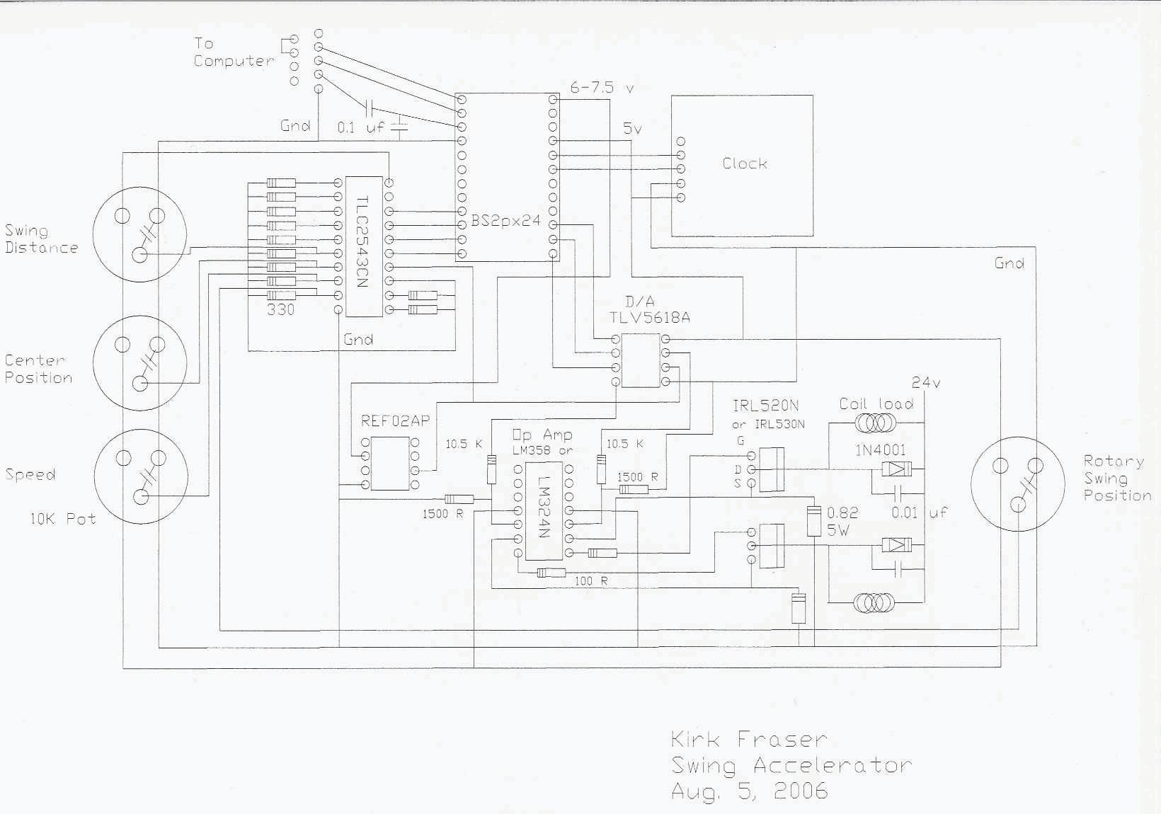
Attached is a circuit diagram.· Sorry the CAD outputs only to print so·I had to scan it back in which resulted in low quality.· All help·appreciated.
Kirk Fraser
I have tried lots of things to get this far including mounting seperate A/D chips on each pot with a double-sided mini PC board I made and several ground loop attempts.· Now I have proven it's the A/D chip that is finnicky by tracing with·the voltmeter starting with the pot.·
Attached is a circuit diagram.· Sorry the CAD outputs only to print so·I had to scan it back in which resulted in low quality.· All help·appreciated.
Kirk Fraser
1640 x 1150 - 140K
Comments
One thing that jumps out at me when looking at your schematic is that there is a 330 ohm resistor (?) attached to every analog input, and the other side of all of those resistors are bussed together and attached to the (-) reference input on the ADC. hmmm. It doesn't look like the (-) reference of the ADC is attached to anything else, not to ground, unless the schematic violates the cross & not connect rule.
Either way, there should not be 330 ohm resistors connected like that. They would swallow any signals from your potentiometers.
▔▔▔▔▔▔▔▔▔▔▔▔▔▔▔▔▔▔▔▔▔▔▔▔
Tracy Allen
www.emesystems.com
The wiper it is not obvious from the drawing. I'd first like to know if you are actually reading a voltage change from GND to VDD on the wiper as you turn it. I know you said you metered it but just wanted to make sure you read it at the a/d's input to verify the full change is getting there. Reading 5118 would first suggest that it is getting a fixed voltage at all times if it is transmitting correctly to the stamp. Having the 330 bussed together sure seems like it would average all the voltages together and prevent the circuit from working. I looked at the datasheet and think you might have some errors with your schematic. Take a fresh look at the ref inputs, and try ditching the 330's and bring the wiper straight in.
I moved the Stamp and A/D chip back to my prototype board (with no resistors) and after thorough testing using the Stamp, voltmeter, and LED's on the serial lines, it appears the A/D chip is dead.· Not only so, chips from both ends of my supply tube all reported 0 on every position when they were tested.· So it appears my whole supply is gone and that chip is too brittle for me.· Any recommendation for another chip & manufacturer?
I'll be using skills learned with your help on the next chip assuming it uses serial communication.· Thanks.
Hi Originator99,
Yes, the 10K pot works great by voltmeter between ground and wiper as I turn it.· The 5118 must be an artifact of Tracy's conversion formula.· I removed the programmed formula and 330 ohm resistors when working with my prototype board and the answers are all zeros on each channel, every chip tested so far.· I consider the chips dead and I've ordered new samples from Linear.·
Attached is a photo of my prototype board in case you see an error.· Thanks.
Kirk
PS: Here's my test code.
' {$STAMP BS2px}
' {$PBASIC 2.5}
' {$PORT COM1}
'Test A/D Inputs
' A/D pins
ADclk········ PIN 11
ADdati······· PIN 10
ADdato······· PIN 9
ADcs········· PIN 8
'VARIABLES
ADch········· VAR Nib
ADout········ VAR Word
DO
·· GOSUB Read_Inputs
·· PAUSE 200
LOOP
Read_Inputs:
FOR ADch = 0 TO 10· 'Read 11 analog inputs as digital 0 to 4095
· LOW ADcs········································· ' select chip
··· SHIFTOUT ADdato,ADclk,MSBFIRST,[noparse][[/noparse]ADch<<8\12]···· ' output AD channel #
··· SHIFTIN ADdati,ADclk,MSBPRE,[noparse][[/noparse]ADout\12]········· ' input pot value
· HIGH ADcs········································ ' deselect chip
····· DEBUG "Ain #",DEC ADch, "· D12 ",DEC ADout, REP 32\5,CR
NEXT
RETURN
Do those LEDs attached to the i/o lines p8 to p11 have built-in resistors? If not, that would be trouble--they are connected directly from the BS2px pins to ground. Also, it looks like the potentiometer at the right is off by one row.
▔▔▔▔▔▔▔▔▔▔▔▔▔▔▔▔▔▔▔▔▔▔▔▔
Tracy Allen
www.emesystems.com
Just wanted to say that I don't think the TLC2543 is a "brittle" chip. I have abused the ever-loving you know what out of that chip, and the only failure I ever had was my fault in a big way. In that case, a mis-wired voltage divder allowed 30+ volts to an input.
Jonathan
▔▔▔▔▔▔▔▔▔▔▔▔▔▔▔▔▔▔▔▔▔▔▔▔
www.madlabs.info - Home of the Hydrogen Fuel Cell Robot
I have about $200 worth of TLC2543 and have tested several both new and used, all with the same result, all zeros.
Tracy,
The debugger result was the same before and after adding the LED's -- all zeros. The LED's helped me to realize the Stamp wiring is correct and the chip isn't responding. Had the pre-LED result not equalled the post-LED result, I'd certianly add resistors as suggested. The tiny pot's wiper really is connected to the TLC2543 input positon 11 -- I noticed a shadow of the wires on the photo in that area.
Johathan,
I'm glad you have had great results so far but in my case either there's a problem with the TI production batch or my environment because both used and brand new chips right out of the tube fail the same. I did have success with this chip when working with Tracy several months ago which is why I ordered more than samples. So far I can't explain why it no longer works for me. I too have abused my BS2PX24 and I'm very happy it still works. (I hope the next Parallax Stamp will include higher resolution A/D on each pin.)
Kirk
▔▔▔▔▔▔▔▔▔▔▔▔▔▔▔▔▔▔▔▔▔▔▔▔
Tracy Allen
www.emesystems.com
See attached Tek scope photo.· I'm not certian the 11 blips are coming from the TLC2543 or the Stamp, possibly by crosstalk.· The pin 19 is left unconnected·according to the best application documentation I know of: http://www.emesystems.com/OL2tlc2543.htm
Tracy,
True, it's entirely possible TI is not at fault, that's just one of the feasible sources of error on my list.· Perhaps ettiquette suggests not adding that to the list of things to consider until all else is eliminated but I tend to list everything first and then eliminate.· It is very possible the humidity here ruined my parts as·an old dot matrix·ribbon·printer which worked fine was placed in an unused room for storage over a winter and when I tried to use it again it was dead and·stayed dead.··But since·this computer, a TV, and other electronics work over time in·my living·room, I'm·not sure·humidity is·the·problem.
Kirk
I don't see that you have direction(DIRS) set for your output pins anywhere in the code.
add this:
OUTPUT 8
OUTPUT 9
OUTPUT 11
Is that the Stamp's Data In pic? If you have a dual trace try reading both in and out. Did you zoom in to see if there was any data hidden inside of the blips?
Test to see if the clock is getting to the A/D as well.
Test CS\ as to see if it is changing states.
Test the SDI for data received at the A/D, if yes, Test SDO again at both ends of the jumper.
Post Edited (originator99) : 8/21/2006 11:45:02 AM GMT
SHIFTOUT ADdati,ADclk,MSBFIRST,[noparse][[/noparse]ADch<<8\12]     ' output AD channel #
    SHIFTIN ADdato,ADclk,MSBPRE,[noparse][[/noparse]ADout\12]          ' input pot value
It is a common mistake. Try that and see if it makes a difference. The potentiometer still does look to me off by one row in the photo.
It is right to keep an open mind and a mental list of possible causes, or multiple sufficient causes, for things to go wroing. In my lists, a bad part from the manufacturer and conditions of storage are quite low on the list. The observation that "It worked before" is always an important consideration. And it is always handy to have a part or two on hand for backup as a sanity check. Not so much as a check on the manufacturer as a realization of the fact that it is the early stages of experimentation that are most likely to smoke a part. I smoked my first propeller chip by setting the developement board on top of a paper clip.
▔▔▔▔▔▔▔▔▔▔▔▔▔▔▔▔▔▔▔▔▔▔▔▔
Tracy Allen
www.emesystems.com
Thanks for your many suggestions. As for the solution, read on!
Tracy,
Congratulations and thank you again. I remember I switched the order of the dati and dato from your specification on http://www.emesystems.com/OL2tlc2543.htm to more closely match the TLC2543 data sheet since that pinout is easier for me but I forgot to check for any consequences to that change later in the code. At this point it totally passed by me. Thanks for catching it.
The test setup is now working so I should be back to where I was soon. The pot is reporting values from 2413 to 2459 at position #10 (0 to 10) or 11. I was hoping for more precision from a stationary pot. The positions wired to GND report 8 to 10. The positions wired to 5v (HI) report 4095 only which is correct. Have you a suggestion to narrow down the results to a single value like the stable HI value? I don't want to have to toss 50 points of this resolution. The pot is still acting like an antenna for static or?
Kirk
Sid
Also to add to what Sid said, if you are using the 3M breadboard setup as in the earlier photo, there is a long ground loop to the potentiometer. The BS2px is a power hungry beast, and it puts spikes of noise on the power supply lines, in particular on the ground line. Since your setup has strong evidence of noise, you have to think of how it is getting in there. Multiple causes are likely. It could be from ground bounce, or from electromagnetic pickup from the high frequency BS2px, or from AC in your room, or from a local radio station, etc. etc.
Are you familar with the notion of star wiring? You have to be careful about the distribution of power, when a sensitive analog circuit and a high speed digital circuit share it. You want to separate the analog and digital wiring onto two branches of a star that radiates out from your power supply. The wiring to your analog to digital converter and the ground(s) for the signals source(s) will be on one rail of the protoboard, and digital wiring to the BS2sx and the power controller on another rail. The power supply connections to those two rails should be connected to the power supply right at the power supply source. I am not sure what the terminals are on that 3M breadboard. Also be liberal with bypass capacitors on both the analog and digital supplies. Keep the wiring to your potentiometer short, or if necessary, use a shiellded twisted pair. I think we got into that in the earlier thread, didn't we?
http://forums.parallax.com/showthread.php?p=550065
▔▔▔▔▔▔▔▔▔▔▔▔▔▔▔▔▔▔▔▔▔▔▔▔
Tracy Allen
www.emesystems.com
Thank you. It's amazing how forgetful I'm getting. I put 2 capacitors on it, one right at the pot and one at the chip. It appears either one cut the response spread down from 40+ to about 10+ points with rare exceptions to 30+.
Tracy,
Yes indeed it is great to hit the nail on the head, thank you! Now even the formerly unlit and hard to see LED's are flashing with data.
Based on working with my scope, it appears there is a lot of stray noise in this room -- if there's any radio noise it's from a ham radio, not a broadcast station anywhere nearby. Sometimes when I drive by a certian spot downtown it kills all AM reception - I don't know what that noise comes from. I tried shielded cable with one end grouded as you suggested but it didn't seem to reduce the noise here. I'm also trying various Radio Shack automotive noise suppressor devices but I haven't found one that works as well as a 0.1uF capacitor yet.
It does appear to affect the result based on exactly where I put capacitors so I am going to be more liberal with them. I moved some to simulate your star wiring idea and that seems to help a little also. One thing that helped in my application is grounding large chunks of metal near the far-flung pots -- my hydraulic parts. Moving the TLC2543's out to be near the pots I'll try again now that my programming error is solved.
The serious problem is in my robot which is no toy, error can mean death. So I have to program around the error hoping it doesn't creep in to the first two digits and 40 reliable positions in 360 degrees isn't much. But having 11 channels per chip is economical. Trying to cut error down to 10% in a way I can use will take both bit math and averaging. I wonder how disk drive makers do it accurately?
It appears low-cost digital position sensors are just pots with different outputs. The ones based on optical sensing could be more reliable but are too large and too expensive for a simulated human hand for example. I remember in the 1970's seeing an ad in Scientific American by HP about a dual frequency laser distance measuring device -- nowdays with toy lasers for $1 retail, there should be a better way to get position than a pot. Does anyone know how the position sensors in optical mice work?
Kirk
ADout = ADout */ $01C3 / 20 ' +-1 degree of error
This returns 360 on 5v and 0 on 0v. A simple loop repeating 3 times to average the answer will minimize jitter from a potentiometer.
It is possible that Bean's suggestion to go with an 8 bit A/D may work as accurately but at least the 11 channels per chip makes this one economical. Any suggestions for a better formula to squeeze more accuracy out of it?
Kirk
▔▔▔▔▔▔▔▔▔▔▔▔▔▔▔▔▔▔▔▔▔▔▔▔
Tracy Allen
www.emesystems.com
Sid
Thanks for the formula. I tried it and had to adjust it to ADout ** 5760 to remove the tenths as that decimal position varies randomly in a loop with no pot motion.
Interestingly the formulas behave differently in terms of error. Mine appears to round up and yours rounds down even after averaging and programmed head to head they don't always show error on the same values.
Trying to minimize errors reported, I found ADout ** 5769 slightly better than my formula in short tests on the same sensed values then averaged. I don't know why, just fewer deviations from the most common value occur.
Unfortunately random errors still creep in, some wildly off. So I suppose the program that makes use of these values will still have to repeat frequently to catch and correct errors mid-execution.
Kirk
I ran a more comprehensive test and found ADout ** 5760 to 5762 has higher upto double the error rate of my formula but using 5763 to 5770 yeilds less than half the errors. One example: when my formula reached 1000 errors, 5763 showed 397 errors. So over time our collaborative formula will produce better results than either seperately.
Kirk
With values of tenths, you can round either up or down.
ADout = ADout ** 57600 ' +/- 0.1 degree, 0 to 3600
ADout = ADout + 5 / 10 ' round off
I can understand that you might need to adjust the proportionality constant to give the most accurate result.
That result that one formula gives more stability than the other is puzzling. It probably has nothing to do with the formula itself, and more to do with numerical roundoff error. If you use a voltmeter to measure, say 1 volt, there will be a point between 0.999 and 1.000 where the meter will bobble back and forth from one reading to another. This is a similar thing, accentuated by the integer math in the Stamp. But if it gives you a more useable result, okay.
I you are going to spot averaging, it is best to do the average at the highest resolution possible, and then round off at the end. You didn't say how you are going to do it. Don't average the values that are already rounded off. Also, if the error is in fact due to power line pickup, it is best to do an average of an even number of points that spans the period of one AC cycle. That is, 16.6667 milliseconds for 60 hz power. To do that on the BS2px, you call the ADread routine 8 times (say) and add evenly placed pauses to place the samples 2.083 milliseconds apart. That has the effect of cancelling out 60hz pickup. And the averaging helps with other random noise too.
Take Sid's suggestion a step further, and add additional lowpass filtering at the inputs. At the ADC input for example, you could have the 0.1uf capacitor and also a 1 meg resistor out to the potentiometer. That would make a strong lowpass filter to get rid of more of the noise before it gets converted to digital by the sampling ADC.
▔▔▔▔▔▔▔▔▔▔▔▔▔▔▔▔▔▔▔▔▔▔▔▔
Tracy Allen
www.emesystems.com
Sid
Sid
▔▔▔▔▔▔▔▔▔▔▔▔▔▔▔▔▔▔▔▔▔▔▔▔
Sid Weaver
Do you have a Stamp Tester yet?
http://hometown.aol.com/newzed/index.html
·
Thanks for the ideas but now I'm confused. I put a 330 ohm resistor between the pot wiper and the A/D chip's last input. The 1M resistor I put between the input and ground in parallel with a 0.1uF capacitor -- is that correct?
Then running the result on my error count program shows my formula is now the better, which I also don't understand.
Tracy,
Ok, I'll have to adjust my averaging formula to operate before rounding. Perhaps that will reduce my confusion on which formula is best for all occasions.
I bought a Parallax clock so I should be able to figure out the timing soon using that if I can't get it from my scope. Thanks.
Kirk
If I can't get the extra digit to stablize, I'll of course live with what I have and finish the robot projects then maybe go for higher resolution later.
Kirk
You will probably have to use the 'scope to adjust the exact timing for getting 2n samples in 16.7 milliseconds. The time between samples will have to be padded with a dummy PULSOUT command, with the duration adjusted to fit. You can observe the CS\ signals on the 'scope.
▔▔▔▔▔▔▔▔▔▔▔▔▔▔▔▔▔▔▔▔▔▔▔▔
Tracy Allen
www.emesystems.com
Ok, thanks for the clarification. I tried my plastic pot which is larger than the one on pictured and it seemed to have two effects. One was approximately half a digit improvement or so on more than half the averaged values as they appear to stay nearer the most common value but occasionally even 8 averaged values are way off.
I don't like that error considering the prospect of human harm when it goes way wrong. An example of an 8 value error is 281 where the most common value is 321. There must be some other math than averaging which can take care of that, Standard Deviation perhaps? Throwing out the furthest values from a sequence? Fuzzy math where ranges of values are used instead of specific values?
Since my wireless internet connection comes and goes too, I'm trying your circuit before I send this. I'm not currently using shielded cable since I'm still on the prototype board.
Ok, great! The 1M resistor in the right place improved results a lot. There are still serious deviations but the tenths of a degree looks usable now. An example of serious deviation sequence: 2052 1796 2054 -- this is with averaging 8 values after collecting the data as you suggested.
You wrote some pots work better than others -- please recommend a pot that works well for you. My "real" pots are 360 degree BI Technologies 6187 10K plastic pots. The circuit board pots are NTE 500-0349 10K. The advantages of the plastic pot is very long life and full 360 degree rotation so it could be used on a slow motor. I can live with less rotation but not the short life of say Radio Shack pots.
Thanks,
Kirk
1) Any triple where the third is in a couple of the first and the second is way out, reject the second before completing the average.
2) Speed window -- follow motion but reject anything impossible to get to at current speed or maximum speed.
The problem I don't yet know how to program around is quantizing. Let's see -- if I program the triple algorithm as the smallest window and don't try to move the window but percolate every value past it, that would eliminate need for special code at the ends when the bad value is at an end. That moves all rejection calculations to focus only on the second value.
This reminds me of my post in the voice recognition thread. We could do frequency analysis using a FFT, Hartley, or Wavelet program to help categorize the bad values. Sounds like overkill though.
Any other suggestions?
Kirk
You can try "box car" averaging, but I'm not sure how much it will help you. This technique is also known as a "moving average". Any decent statistics book should give examples.
Regards,
Bruce Bates
▔▔▔▔▔▔▔▔▔▔▔▔▔▔▔▔▔▔▔▔▔▔▔▔
<!--StartFragment -->