

Attaching servos directly to stamp
 HavoKane
Posts: 109
HavoKane
Posts: 109
ok, i need some help hooking a couple things up. basicly, im trying to make a simple IR rover without using the BOE. i drew a schematic that illustrates what i have and what i need help with.

edit: IMG isnt showing up, so i added it as an attachment
edit2: fixed the schematic, goin to radio shack now to get the perf board
Post Edited (HavoKane) : 8/3/2006 8:49:11 PM GMT
edit: IMG isnt showing up, so i added it as an attachment
edit2: fixed the schematic, goin to radio shack now to get the perf board
Post Edited (HavoKane) : 8/3/2006 8:49:11 PM GMT
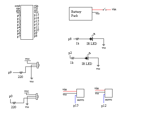
578 x 399 - 10K
Comments
The schematic for the BOE is available online. You might look at it for ideas and "best practices". Parallax has put a two position power switch in the BOE which first supplies power to the Stamp, then to both the Stamp and the servos. They also have a separate regulator that can supply about 1A from a 6V to maybe 9V supply (again, whatever voltage isn't used turns to heat in the regulator).
Post Edited (Mike Green) : 8/3/2006 8:29:16 PM GMT