Propeller Application: Inductive Joystick ... a different twist on LVDT sensors.
 Beau Schwabe
Posts: 6,576
Here is another cool sensor application to play with....
Theory of operation:
Basically this is a variation of a LVDT(Linear Variable Displacement Transformer).
The main difference is that there is no primary coil present, only two secondary
coils. Typically a standard LVDT has three coils. A single Primary and two
secondaries...
...In this configuration a signal is introduced to the Primary, and by transformer
coupling, a ratiometric signal can be detected between the two Secondaries.
How do you do this without a Primary coil?
If the secondary coils form a "tuned" LC circuit with BOTH coils tuned to the exact
same frequency, then the addition or subtraction of a metal object will "detune" the
LC circuit causing the output to dip in either situation.
Note: Adjacent coils at the same frequency will not be affected unless they also
"see" the metal object
But wait, we don't want to tune the coils so that they peak, we just want to tune
them so that they are somewhere in-between. The reason is so that when we add metal,
we want some headroom for the output to increase. Likewise if we remove metal, we want
the output to decrease. It's like tuning a radio to a weak signal, if you position
the antenna just right you can get a good signal, and if you loose your antenna position
the signal is lost. In the case of this LVDT, this is exactly where we want to be.
Now, with this type of tuning, there are two valid locations you can be. On the LEFT
side (somewhere in-between) of peak or on the RIGHT side (somewhere in-between) of peak.
One side will cause the output to increase with the addition of metal, and the other
side will cause the output to decrease with the addition of metal. Here it just depends
on what you want to do with your specific application.
Consider the simple LC circuit below. If the Excite signal (can be a square wave) is
somewhere near the resonate frequency of the LC values, then you will see a noticeable
peak on your scope. It is not uncommon for a 3.3 Volt "Excite signal" to induce a 30
Volt to 100 Volt signal on the output when the resonance of the circuit agrees. This
in a sense is your primary and secondary coil rolled into one, acting as a step-up
transformer.
Now, consider two of the above circuits coupled together via diode in a way where one
circuit captures the "top" half of the sine wave, while the other circuit captures the
"bottom" half of the sine wave.
...The output now can represent the magnitude of both tuned circuits in a differential
relationship to one another. One slight problem however... The Output swings above
and below VSS. For it to work nicely for the Propeller, we want the output to swing
from VSS to VDD. The solution is to create a false VSS in the circuit above equal to
1/2 VDD. A simple resistor divider is enough here to do the trick.
▔▔▔▔▔▔▔▔▔▔▔▔▔▔▔▔▔▔▔▔▔▔▔▔
Beau Schwabe
IC Layout Engineer
Parallax, Inc.
Post Edited (Beau Schwabe (Parallax)) : 7/31/2006 9:34:35 PM GMT
Theory of operation:
Basically this is a variation of a LVDT(Linear Variable Displacement Transformer).
The main difference is that there is no primary coil present, only two secondary
coils. Typically a standard LVDT has three coils. A single Primary and two
secondaries...
          Primary
          └──┘
       ─  ─
     ┌──┐    ┌──┐
   Secondary  Secondary
...In this configuration a signal is introduced to the Primary, and by transformer
coupling, a ratiometric signal can be detected between the two Secondaries.
How do you do this without a Primary coil?
If the secondary coils form a "tuned" LC circuit with BOTH coils tuned to the exact
same frequency, then the addition or subtraction of a metal object will "detune" the
LC circuit causing the output to dip in either situation.
Note: Adjacent coils at the same frequency will not be affected unless they also
"see" the metal object
But wait, we don't want to tune the coils so that they peak, we just want to tune
them so that they are somewhere in-between. The reason is so that when we add metal,
we want some headroom for the output to increase. Likewise if we remove metal, we want
the output to decrease. It's like tuning a radio to a weak signal, if you position
the antenna just right you can get a good signal, and if you loose your antenna position
the signal is lost. In the case of this LVDT, this is exactly where we want to be.
Now, with this type of tuning, there are two valid locations you can be. On the LEFT
side (somewhere in-between) of peak or on the RIGHT side (somewhere in-between) of peak.
One side will cause the output to increase with the addition of metal, and the other
side will cause the output to decrease with the addition of metal. Here it just depends
on what you want to do with your specific application.
Consider the simple LC circuit below. If the Excite signal (can be a square wave) is
somewhere near the resonate frequency of the LC values, then you will see a noticeable
peak on your scope. It is not uncommon for a 3.3 Volt "Excite signal" to induce a 30
Volt to 100 Volt signal on the output when the resonance of the circuit agrees. This
in a sense is your primary and secondary coil rolled into one, acting as a step-up
transformer.
                    L     C
    Excite signal ───┳── VSS
                        │
                        └─── Scope
Now, consider two of the above circuits coupled together via diode in a way where one
circuit captures the "top" half of the sine wave, while the other circuit captures the
"bottom" half of the sine wave.
                    L     C
                 ┌────┳── VSS
                 │      │
                 │      └─├───┐
  Excite signal ┫               ┣─ Scope
                 │      ┌─┤───┘
                 │  L   │  C
                 └────┻── VSS
...The output now can represent the magnitude of both tuned circuits in a differential
relationship to one another. One slight problem however... The Output swings above
and below VSS. For it to work nicely for the Propeller, we want the output to swing
from VSS to VDD. The solution is to create a false VSS in the circuit above equal to
1/2 VDD. A simple resistor divider is enough here to do the trick.
▔▔▔▔▔▔▔▔▔▔▔▔▔▔▔▔▔▔▔▔▔▔▔▔
Beau Schwabe
IC Layout Engineer
Parallax, Inc.
Post Edited (Beau Schwabe (Parallax)) : 7/31/2006 9:34:35 PM GMT


Comments
Depending on how you read in the signal, it's porportional to the amount of metal being added / subtracted, correct?
How sensitive is the circuit in terms of the amount of motion it will detect?
▔▔▔▔▔▔▔▔▔▔▔▔▔▔▔▔▔▔▔▔▔▔▔▔
Propeller + Hardware - extra bits for the bit bucket =· 1 Coffeeless KaosKidd
·
providing a full scale range from 0-65535. Also, by design, this configuration is very temperature stable."
So the answer is very sensitve, 16 bits worth.
▔▔▔▔▔▔▔▔▔▔▔▔▔▔▔▔▔▔▔▔▔▔▔▔
...
Sweet....
▔▔▔▔▔▔▔▔▔▔▔▔▔▔▔▔▔▔▔▔▔▔▔▔
Propeller + Hardware - extra bits for the bit bucket =· 1 Coffeeless KaosKidd
·
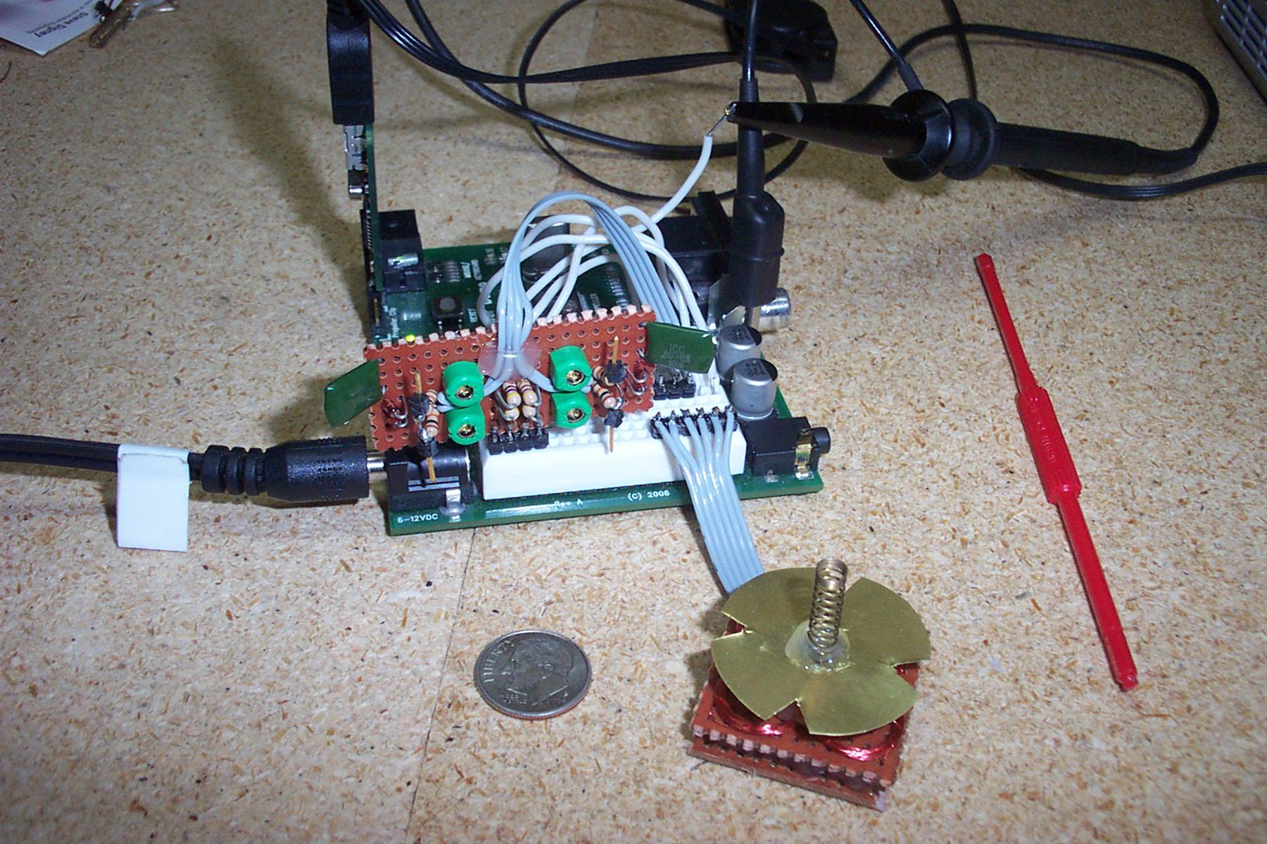
The image here...
http://forums.parallax.com/attachment.php?attachmentid=42702
...shows a brass "disk" with 4 notches.· The Notches are not necessary,
I originally thought that I might need to bend these flaps down closer to the coils to increase the sensitivity.
Not the case however, so this could be a solid disk.· The disk sits about 1/4 inch above the coils and is simply
hot-glued to the spring/joystick.· See just the spring and coils below...
To further clarify, the RAW full scale range is from 0-65535, but there is plenty of noise
in that.· By the time you scale it down to 8-bit resolution it's rock solid. The LSB
might bounce but that's expected behavior.
▔▔▔▔▔▔▔▔▔▔▔▔▔▔▔▔▔▔▔▔▔▔▔▔
Beau Schwabe
IC Layout Engineer
Parallax, Inc.
Post Edited (Beau Schwabe (Parallax)) : 8/1/2006 7:25:47 PM GMT
Thanks for explaining that...
(Sorry it took so long to get back to you... Twas out in the midwest... I was in Altanta, GA Friday... very bad TBoombers shut down the airport...)
▔▔▔▔▔▔▔▔▔▔▔▔▔▔▔▔▔▔▔▔▔▔▔▔
Propeller + Hardware - extra bits for the bit bucket =· 1 Coffeeless KaosKidd
·