

Desire output to CRT monitor
 Harley
Posts: 997
Harley
Posts: 997
I got my PropSTICK going with the It's Alive/PropSTICK demo  , and ran across the Monitor.spin and found it dumped memory contents. Super.
  But not what 'monitor' I was hoping for.
 I have a 5.5" monitor I'd like to view some demo(s) with. I ran across the circuit PhiPi suggested (1.1K, 560, and 270 resistors between pins 12, 13, and 14 and the RCA jack) and added that to my protoboard, see pic.
But, when I run TV_Terminal.spin there is no signalling present (using scope to view). Is there a proper program to work with these pins and the CRT monitor?
▔▔▔▔▔▔▔▔▔▔▔▔▔▔▔▔▔▔▔▔▔▔▔▔
Harley Shanko
h.a.s. designn
, and ran across the Monitor.spin and found it dumped memory contents. Super. But not what 'monitor' I was hoping for. I have a 5.5" monitor I'd like to view some demo(s) with. I ran across the circuit PhiPi suggested (1.1K, 560, and 270 resistors between pins 12, 13, and 14 and the RCA jack) and added that to my protoboard, see pic.But, when I run TV_Terminal.spin there is no signalling present (using scope to view). Is there a proper program to work with these pins and the CRT monitor?
▔▔▔▔▔▔▔▔▔▔▔▔▔▔▔▔▔▔▔▔▔▔▔▔
Harley Shanko
h.a.s. designn
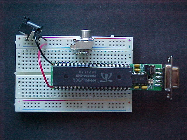
640 x 480 - 71K
Comments
There are several demo programs in the Propellor Tool library that gets installed when you install the Propellor Tool. All of them have "demo" in their names. These are the main programs that "do stuff". TV_Terminal.spin in particular is an "object" that implements a low resolution text display with the help of another "object" called TV.spin. Look at the demo programs and make up your own by modifying them.
Without a main program to call it properly, you won't get any video output with TV_Terminal.spin by itself. Try TV_Terminal_Demo.spin as your main (or current) program. Another demo you should try is Graphics_Demo.spin. This uses an "object" called Graphics.spin that provides low resolution graphics including sprites, vectors, shapes, all in colors and it uses TV.spin as well to actually drive the TV outputs.
Unless there were a way to use my PC laptop (a ThinkPad) for display to try these. As far as I'd guess, the connector is only for output to external display, not inputting.
It seems there isn't clear text on all these demo programs. Or maybe it is explained somewhere else.
▔▔▔▔▔▔▔▔▔▔▔▔▔▔▔▔▔▔▔▔▔▔▔▔
Harley Shanko
h.a.s. designn
Most simple monitors are video monitors and will accept the video signal put out by the Propellor. Generally you can tell because they have an RCA Phono jack on them. The programs that have "TV" in their name are intended to be used with a video monitor. The programs with "VGA" in their name are intended to be used with a VGA computer monitor. In the case of TV programs, make sure that they are configured for the pins you've used for your video output. There should be an "xxx.start(12)" somewhere in the main program. This passes the first pin number of a group of 4 that are used for video generation (and audio sometimes). The demo board assumes this is 12. There may have been early versions of these demos that assumed pins 16-19. I think all of the demos installed in the current release of the Propellor Tool assume that 12-15 are used. This is true for TV_Terminal_Demo, TV_Text_Demo, and Graphics_Demo.
Looking at the listing it appears the signals should appear on pins 12 - 15, BUT , on scoping, find there is activity on the 16 - 19 group (actually 16 just looks noisy around ground).
What am I doing wrong? (I downloaded and installed version 0.98.1.)
▔▔▔▔▔▔▔▔▔▔▔▔▔▔▔▔▔▔▔▔▔▔▔▔
Harley Shanko
h.a.s. designn
dan
ps look at the sticker thats supposed to go on top of your prop chip, or at a diagram of the pinouts
Dan's right. The numbers refer to port numbers, not pin numbers. Why not attach the chip label that came with your PropSTICK kit, so you can identify the pins more readily?
-Phil
OK, I now understand the confusion. The chip label has it as A0...A31. But when I saw Phil's schematic for the 3 resistor/RCA jack it was listed as P12..P14, which I assumed was for pin numbering. Beginner's misunderstandings .... and Murphy's law at work!!
Scoping at the RCA jack, I see the 4 levels of signalling. Cool Propeller.
▔▔▔▔▔▔▔▔▔▔▔▔▔▔▔▔▔▔▔▔▔▔▔▔
Harley Shanko
h.a.s. designn
'Sorry about that! I used "P" to stand for "Port". "A" would've been less ambiguous.
-Phil
Wonder what the "A"s stand for, then?
Now I see the reason for the label. I didn't want to cover the Propeller IC top markings until I got a good picture of that image. I suppose what image I included with my first queries is adequate.
Label time now. (I noted when I removed the 'insulator' for the crystal, it didn't have a 'sticky' side, just 'torn paper appearance. I'll have to be move careful when I remove the label.)
Attached pic shows it working. Used to be a whole 40-pin DIP (think it was a moto 6847 was required to do such things. Now a COG does it, and much more. (Haven't yet seen if 'COG' is an acronym or what?)
▔▔▔▔▔▔▔▔▔▔▔▔▔▔▔▔▔▔▔▔▔▔▔▔
Harley Shanko
h.a.s. designn
It stands for "Port A". You may have noticed in the register descriptions in the docs that there's mention of a Port B for "future use".
I'm glad you told me about the crystal insulator. I may be cutting too deeply into the backing. Just be sure when you peel off the chip label to bend the backing back a bit until one corner pops free, rather than digging in with a fingernail. That will prevent the backing from delaminating.
-Phil
In all the confusion, witch pins did you use to connect your prorstick to your CRT?
Rob7
Don't know what happened, but thought I already replied.
Originally I did have the resistors connected to 'pins' 12 - 14. Which are 3.3v, A8 - A10.
Once I fixed the problem, it is NOW on pins 17 - 20, A12 - A15, that last for 'audio'. Which let me see the TV_Terminal and Graphic demos. Of course, with a b/w monitor it was 4-color gray. But, enough to indicate that things were OK.
Impressive. Yet, it sounds like the Hydra demos will be very interesting. Amazing that the Propeller has such power.
▔▔▔▔▔▔▔▔▔▔▔▔▔▔▔▔▔▔▔▔▔▔▔▔
Harley Shanko
h.a.s. designn
Thanks for the info. Awaiting also for the Hydra system. Can't wait.
Thanks again.
Rob7