

SX20 Adapter
 Tony Leyland
Posts: 71
Tony Leyland
Posts: 71
Hi,
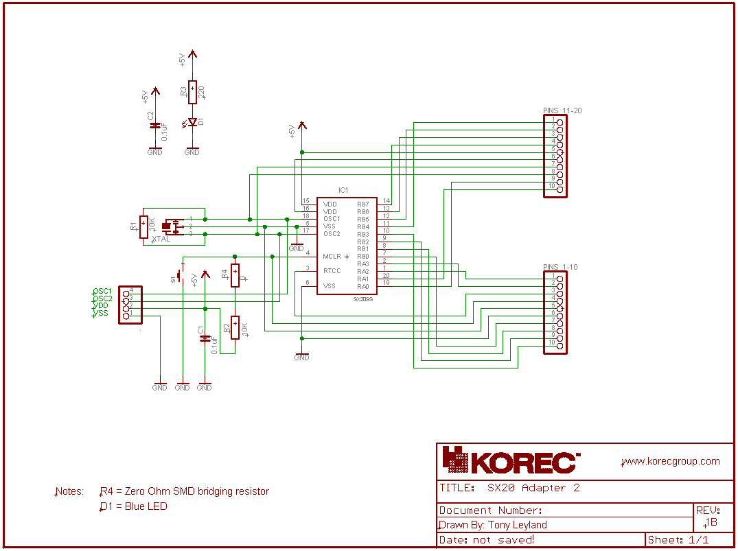
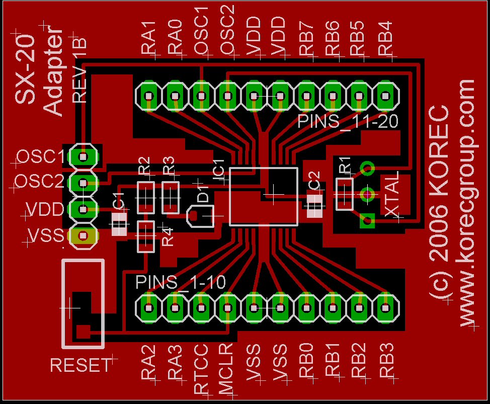
As promised, here is the schematic and PCB layout of an SX20 Adapter I produced to test the
Toner Transfer System (www.pulsar.gs/) I was going to use to produce prototypes of my projects.
My original question and help received, can be found in this thread:- http://forums.parallax.com/showthread.php?p=582972
The schematic and PCB layout was produced with the Free Lite version of EaglePCB V4.16r1 (www.cadsoft.de/), which
I downloaded to evaluate and to learn PCB production. I've since upgraded to the Standard edition, since my future designs will be
used in a comercial environment.
There was some interest generated when I mentioned about sharing this design, so here it is. It may be freely used for non-profit use.
Cheers
Tony

Comments
manual about using 'busses' in the diagram - much easier on the eye now !) It's also the first time I've produced a custom PCB
rather than using the Vero strip board techniques.
I found that using SMD components was not too difficult to handle. Using the 0805 series was a nice size to
deal with - Some of the other SMD series where so small, that they would of been very awkward to handle.
I was a bit surprised when I got them how small they were, but with a fine pair of tweezers, a good storage container
and a clean work area, I did not lose any !
So, the equipment I used to make/assemble the board was:-
TTS System from www.pulsar.ds
1/2 Ounce single sided board 0.032" thick (comes with above system).
HP LaserJet 5 for all artwork (including component legend). Bought on eBay as recomended by the creators of the TTS system.
Household iron (for toner transfer onto PCB) - shipping of the TTS laminator to the UK prohibitive due to weight.
Steel wool & Acetone (for copper cleaning).
Ferric Chloride and tray.
Household cleaning sponge to 'stroke' the Ferric Choride on to the PCB to be etched.
Liquid Tin (for tin plating the copper).
32 SWG solder.
SMD Iron with 0.2mm tip (this was the most expensive item).
Flux remover.
Bench magnifying lamp (2.25x magnifier).
SMD Tweezers.
Quite a few things here, but it does not take long to produce the end result.
To answer your question Philip, to actually assemble I just needed the magnifier, the tweezers, the iron with a small tip and a steady hand !
I did try tacking the components in place with a small blob of solder while they were being held in place with the tweezers, but the end
result of the solder joint was not what I wanted.
I opted for a different approach by using a very thin touch of adhesive (2 part epoxy resin) to hold the components in place prior to soldering.
An extra step, I know, which slows things down a bit, but worth it in the end I think. The SX20 was the trickiest to solder, but managed to do one
pin at a time with no bridges. I have read elsewhere on this forum about using a large tip iron and running it along the pins, then cleaning
with a solder wick - not tried this technique yet - I may do when I get to doing an SX48.
I'd recommend to anyone to give it a try if thinking about doing it (if I can do it as a DIYer with my limited experience).
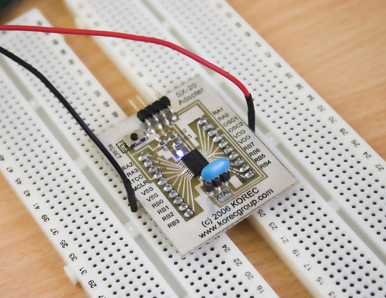
Here are some additional photos of the board, at stages of completion.
Cheers
Tony
That "Liquid Tin" is great stuff ain't it ?
Very nice job, on the PCB.
Bean.
▔▔▔▔▔▔▔▔▔▔▔▔▔▔▔▔▔▔▔▔▔▔▔▔
Cheap 4-digit LED display with driver IC·www.hc4led.com
Low power SD Data Logger www.sddatalogger.com
"I reject your reality, and substitute my own." Mythbusters
·
Yes I agree, the liquid tin stuff is cool and works really quick and does a good job of protecting the board as well as
helping with the soldering.
One extra step would be to spray with clear PCB laquer to protect further or even better the green spray enamel that Pulsar show on their
site. I tried to get hold of some (Testors Candy Green), but the US shop would not send overseas due to it being combustible and
the UK distributor would only sell a pallet of 24 minimum :-(
Tony
nice design, and good job on etching/soldering that board.
My only concern are the relatively long traces for OSC1 and OSC2. From the crystal, they are routed all around the board, to the upper header pins, to the SX-Key header, and to the SX20. Thisa may cause pretty much EMI especially on a single-sided board. When you are going to make a re-design, I'd suggest to place the crystal and the SX-Key header at one side of the board, and maybe do not route the OSC1/OSC2 signals to the upper header at all unless you have a specific reason why you need them to be available there.
▔▔▔▔▔▔▔▔▔▔▔▔▔▔▔▔▔▔▔▔▔▔▔▔
Greetings from Germany,
G
Thanks for the advice. Yes the XTAL tracks are are a bit long, they are probably acting like little aerials for the 50hz clock !
I will make sure that my future designs give out less EMI. My next mini-project will be an FTDI 232RL IC adapter made in a
similar way to this one, before attempting to solder an SX48 onto one of my designs.
I know what you mean about the copper pouring - it took me ages to work out how that was acheived.
Cheers
Tony