

Playstation Controller to Propeller
 Red-327
Posts: 1
Red-327
Posts: 1
Has anyone connected a Playstation Controller to the Propeller successfully yet?
The picture below is how I was trying to connect two controllers to the BS2p Stamp, which I have not successfully completed yet.· Once I saw the Propeller I decided to stop working with the BS2p.
Thanks,
▔▔▔▔▔▔▔▔▔▔▔▔▔▔▔▔▔▔▔▔▔▔▔▔
Ringo Klassen
The picture below is how I was trying to connect two controllers to the BS2p Stamp, which I have not successfully completed yet.· Once I saw the Propeller I decided to stop working with the BS2p.
Thanks,
▔▔▔▔▔▔▔▔▔▔▔▔▔▔▔▔▔▔▔▔▔▔▔▔
Ringo Klassen
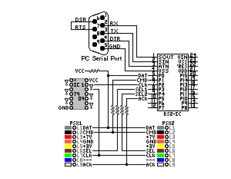
900 x 700 - 122K
Comments
▔▔▔▔▔▔▔▔▔▔▔▔▔▔▔▔▔▔▔▔▔▔▔▔
"It is not necessary to change. Survival is not mandatory."
- W. Edwards Deming
I did this with a BS2 for a "macromouse" project that I did - long before commercial macromouse product even existed. What I did was connect a playstation controller to the board from a mouse using a Basic Stamp. The Stamp would read the playstation controller and then fake the mouse circuit board into thinking someone was moving the mouse and clicking buttons. The stamp would record all of your movements into a "macro" which you could later play back.
I've attached the entire source code for the project to this post, you're welcome to re-reverse engineer the PSX controller stuff from it. Essentially, the PSX controller makes an IDEAL controller for interfacing to a microcontroller project:
- PSX2 controllers and analog controllers are backwards compatible with the PSX1 controllers. Essentially, if your code knows the older PSX1 controller's protocol, it will still work with newer controllers too!
- The controller uses synchronous clocked logic with the microcontroller as the clock, so there're few timing issues involved.
Basically, it's so simple, all you have are 3 pins to worry about. You pull the Attention pin low when you want to get the PSX controller's attention. Then you cycle the CLOCK pin on the controller at whatever speed you want, while putting bits one at a time on the data line. You send a magic number in this way, and then the controller sends back another magic number and the 16 bits following that can be stored in a variable; they will be 1 or 0 depending on which button is pressed. There are comments in the source code I attached which explain the magic numbers and what button each bit position represents. That's all there is to it.
Since the program is huge (the biggest Stamp program I've ever written), and the controller code is not all in one place, I'll highlight the important functions here:
The signals coming from the controller are open collector TTL signals. You need to use 2.2K pull up resistors to bring the outputs up to VCC (i.e. 3.3 volts) when they are off, otherwise instead of 0 and 1 your logic levels will be 0 and "sort of 0". Needless to say you would only read garbage. It's easy to forget them - I did on my automouse.
Also, I sucessfully ran a controller off 5 volts for the automouse project, but I think that the playstation controller actually expects a 3.3 volt supply anyway, so just power the controller from the same supply as the prop.