

Testing a stepper but no torque
 T Chap
Posts: 4,260
T Chap
Posts: 4,260
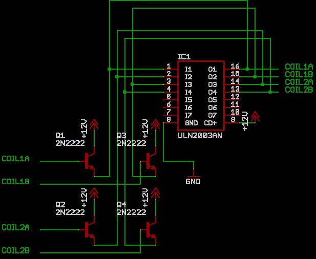
I just hooked up a BS2P40 to a LIN engineering 4218L Nema 17 stepper to learn how to run motors directly off a processor. I found the schematic below somewhere and it works in a functional sense, surely not enough current though. The motor is spinning around smoothly using the code shown, but it has absolutely no torque, and this is supposedly their "high torque" 17 version.
With the code shown below, I can't start it up sith less that PAUSE 3, but once it is running at 3, it will accerate using PAUSE 2, but pause 1 will not run, just vibrates. There must be something I am overlooking. Maybe the small transistors are't enough to give it enough torgue, but that shouldn't stop if from spinning faster? Maybe not the best logic.
Maybe somebody will see something I am missing. Lets assume that it is the small transistors, that is easily solved. But, what about the slow RPM due to the slow speed of the stamp? I am having a hard time thinking of a way to send this code sequence and faster.
[noparse][[/noparse]code]
COIL1A VAR OUT0 'red coil1
COIL1B VAR OUT1 'blue coil 1
COIL2A VAR OUT2 'green coil 2
COIL2B VAR OUT3 'black coil 2
MAIN:
'RAMPS UP FROM HERE
COIL1A = 1
PAUSE 3
COIL1A = 0
COIL2A = 1
PAUSE 3
COIL2A = 0
COIL1B = 1
PAUSE 3
COIL1B = 0
COIL2B = 1
PAUSE 3
COIL2B = 0
LOOP2:
COIL1A = 1
PAUSE 2
COIL1A = 0
COIL2A = 1
PAUSE 2
COIL2A = 0
COIL1B = 1
PAUSE 2
COIL1B = 0
COIL2B = 1
PAUSE 2
COIL2B = 0
GOTO LOOP2
617 x 506 - 76K
Comments
The motor coil sequence actually running is:
COIL1A 1
COIL1A 0
COIL2A 1
COIL2A 0
COIL1B 1
COIL1B 0
COIL2B 1
COIL2B 0
1 is energized, 0 is off
I would want the motor to at any point be able to calculate where it is, apply an acceration curve, ramp up to speed, decel to the position. I may be asking to much for the Stamp to do already. I probably will have to get an SX experiment board for this.
Make sure you know the difference between Bipolar and unipolar steppers and have code that matches the stepper you are using. If you have a unipolar stepper, just run +12v to the common wires, and switch the coils to ground with your Darlingtons. An NPN transistorworks better as a sink rather than a source for the load. Google "Jones on Stepping Motors" to see your options.
torque and speed work against each other with steppers. If you try to go fast(especially from a dead stop), you will get less torque. If you try to go TOO fast, you will skip steps. Try adjusting your pause statements to a bit more time between moves.I If you want higher top speed, you need to "ramp up" the speed over timewith code that gradually decreases the time between steps. The reverse for deceleration.
You code appears to only excite one coil at a time. Try coil sequences that excite more than one. , Jones will also show sequencing options, or look at some code here:
http://www.me.umn.edu/courses/me2011/robot/technotes/stepper/
There are sequences that excite two coils, and sequences that alternate between one and two coils (half step).
You'll Know if your UNL2003 is too small if it gets real hot (or worse, the magic blue smoke gets out).
▔▔▔▔▔▔▔▔▔▔▔▔▔▔▔▔▔▔▔▔▔▔▔▔
At least it turns smoothly, so I can experment with some code. I am trying to get a system sorted out to send out X number of pulses at Y spacing, and find out how to modify the spacing between pulses with a variable.
bipolar junction Transistors need to be used in PNP--NPN pairs to worked properly in an H-bridge
A better choice to drive your stepper would be a 293 B/D ,298, or 754410 IC, or a 297-298 pair.
I refer you back to Jones:
http://www.cs.uiowa.edu/~jones/step/circuits.html
especially the section on "Practical Bipolar Drive Circuits"
▔▔▔▔▔▔▔▔▔▔▔▔▔▔▔▔▔▔▔▔▔▔▔▔
Post Edited (Larry) : 6/9/2006 4:40:18 AM GMT
Try this code also
Run:
High 1
Low 0
Pause 4
High 0
Low 1
Pause 4
Goto Run
Post Edited (bennettdan) : 6/9/2006 7:30:02 AM GMT
Most steppers can be run at 150 - 200% of that rating, praticularly at high speeds.
How many steps/rotation is the motor described as?
(48 is common, but it may be more)
Steppers aren't usually known as speed demons, and pushing it much beyond 200 - 300 RPM may be difficult.
If you find that PAUSE 2 works, but PAUSE 1 doesn't, it may mean you've passed the speed it can work at reliably(may change with a higher voltage) then you may want to try a 'microadjustment' of the ime. Maybe adding a FOR NEXT loop that just increments a counter to waste a bit of time in addition to the PAUSE 1 instruction?
▔▔▔▔▔▔▔▔▔▔▔▔▔▔▔▔▔▔▔▔▔▔▔▔
Don't visit my new website...
This code working pretty good just to get motion, I think with a real driver it will have some good power.
The Nib mentioned in the code below is as follows:
A = COIL 1 A
B = COIL 1 B
C = COIL 2 A
D = COIL 2 B
MOTOR VAR OUTA
Main:
motor = %0101
PAUSE 3
motor = %0110
PAUSE 3
motor = %1010
PAUSE 3
motor = %1001
PAUSE 3
GOTO main
Now that I can make it move in several modes, I want learn what is the best chip do this with, even at the lowest pause speed the Stamp is too slow unless there is a better way to send the pulses than what I described above. I will likely try it with an SX.
Is there a way to set a variable for the pause time so that it can be set logrithmically with a formula? Too bad the pause time can't be smaller than 1, that would help too.
That means about 12instructions for every mS(PAUSE uses mS timing), so wasting a bit of time to equal the time you want shouldn't be that difficult.
(Not all instructions executes at the same rate, so some experimentation is needed)
▔▔▔▔▔▔▔▔▔▔▔▔▔▔▔▔▔▔▔▔▔▔▔▔
Don't visit my new website...
I'll try the Pulsout and see what that does, it would be great ot be able to find a way to exceed 1 millisecond options. Maybe the SX will allow decimal points for pause times.
I'll post what I come up with in a few days along with the new circuit a CNC motor guru is helping me with that will be pretty slick. It will use the EDE 1204, the IR2184 mosfet driver and 8 power 12amp power mosfets. These other guys are saying not to bother with NPN/PNP trannys for a number of reasons.