

Solving the noise issue with vehicle electrical systems
 ERM
Posts: 34
ERM
Posts: 34
Hi Guys,
I've read many posts of people asking about using the Stamp in vehicles or with 12 Volt batteries, and the same issue has come up about the "noise" a vehicle's electrical system puts out, and the potential of frying the Stamp. While many references have been made in adding capacitors or LC filters to the supply line of the Stamp, there have been no helpful schematics.
I’ve made some inquiries and was referred to a website that published an adequate 5 Volt power supply using a vehicle's 12 Volt electrical system. This information was given to me by an engineer that develops electronic flashers for vehicles using microprocessors, and this is how they solve the "noise" issue from the VES. I thought I would share this with everyone, as it could prove helpful to some.
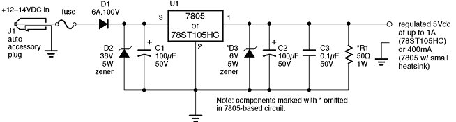
This circuit has 2 set-ups, a 1 Amp supply and a 400 mAmp supply. The info shows a schematic and lists the component's part numbers from Digi-Key as well. Sorry Parallax. [noparse]:([/noparse]
I've read many posts of people asking about using the Stamp in vehicles or with 12 Volt batteries, and the same issue has come up about the "noise" a vehicle's electrical system puts out, and the potential of frying the Stamp. While many references have been made in adding capacitors or LC filters to the supply line of the Stamp, there have been no helpful schematics.
I’ve made some inquiries and was referred to a website that published an adequate 5 Volt power supply using a vehicle's 12 Volt electrical system. This information was given to me by an engineer that develops electronic flashers for vehicles using microprocessors, and this is how they solve the "noise" issue from the VES. I thought I would share this with everyone, as it could prove helpful to some.
This circuit has 2 set-ups, a 1 Amp supply and a 400 mAmp supply. The info shows a schematic and lists the component's part numbers from Digi-Key as well. Sorry Parallax. [noparse]:([/noparse]
654 x 176 - 23K

Comments
http://www.seetron.com/an_vpwr1.htm
▔▔▔▔▔▔▔▔▔▔▔▔▔▔▔▔▔▔▔▔▔▔▔▔
Chris Savage
Parallax Tech Support
csavage@parallax.com
▔▔▔▔▔▔▔▔▔▔▔▔▔▔▔▔▔▔▔▔▔▔▔▔
Thanks, Parallax!
It supplys a minimum amount ( 5vdc/50ohm = 0.1 A = 100 ma) of load to give the regulator some juice with wich to work.
this is often done when a device could be in a state in wich no current is sinking trough, in this evenience the regulator
finds itself in a state of no or poor regulation ( in the response time of the circuit of course) this could lead to small and repeated
voltage variations well beyond the limits the device could accept, tough this being for a very limited amount of time, it does not fry
the device but strictly relates to the failure rate of most electronics devices and components wich is higher.
On the other hand if one of the specific devices supplyed with the power supply in object, draws continuolsy that or more minimum amount of current the resistor could
be removed, gaining that 100 milliamps of current for the devices if they require.
In many of the new cars being the electronics more and more important, generally out of the factory the noise generated is far less than before, nonetheless the situation is not the same after a period of use(abuse), often the wirings relies on the shielding to diminish the noise levels, but what happen when the shielding is interrupted somewhere due to a rugged use of the car or simply by vibration or elongements of the wiring standoffs? in one or more localized situations it will be a source or a sink of noise not counted for in the designing process, if there is a source, the more noise could interfere with other devices locally or distant a precise amount of centimeters/inches (wavelengt), think what kind of trouble could do some noise raised near a reference voltage + or reference ground of an ADC converter.
If the noise is sinking (i.e. noise generated locally by another device that's interfering with the signals trough the varied impedance of that shielding not more acting as shield but as door.
If in the car are present radio systems such as TX, RX or RTX it could be necessary to put a filter with two coils in series one for each polarity (Vbatt+, ground)
with before the coils, two capacitor of different value say 470 and 0.1 uf and after the same. this helps with the big capacityes absorbing slow frequencies and supplying some juice ready and fast to use while the small one looks for higher frequencies cutting down the general level of radio noise.
Also there is the possibility that radio frequency spills trough the air into the (i.e. vents holes) boxes to the electronic boards contained, to shield in this case is the almost unique tecnology affordable, and shielding of the boxes containing the devices, is quite like black magic, in the sense that being the variables affecting the result soo many, it's often a process of try and change more than a calculation to solve the problem.
hope this has clarified some aspects related at power supplyes specific for supplying electronic devices trough a car common wiring.
Stefano Caruso
Post Edited (ellizard) : 5/25/2006 9:03:07 AM GMT
Now it makes sense. R1 takes the regulator into it's load line,preventing additional switching noise from being added.I wonder why this is not as much a problem with a 7805?
▔▔▔▔▔▔▔▔▔▔▔▔▔▔▔▔▔▔▔▔▔▔▔▔
Thanks, Parallax!
It may not contribute to noise reduction, but from what I have read, anything over 10uf is inviting damage to the regulator at shutdown.
▔▔▔▔▔▔▔▔▔▔▔▔▔▔▔▔▔▔▔▔▔▔▔▔
"When all think alike, no one is thinking very much.' - Walter Lippmann (1889-1974)
······································································ Warm regards,····· G. Herzog [noparse][[/noparse]·黃鶴 ]·in Taiwan