

The AppMod Thingie

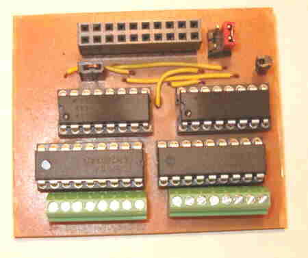
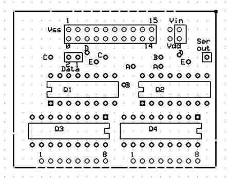
After a couple of false starts and four re-designs, I finally finished my Dual 595/2803 AppMod device.· I have attached a picture of the completed unit and a screen shot showing the connections.
You will note the little wire jumoer·at Data pins 1 and 2.· This would be for the first Appmod.· If you wanted to daisy-chain two or more then the wire jumper would be left out and the Ser out jack on the first board would be patched to Data pin 2, and so on.· You could stack up to five boards, giving you 80 Hi-Lo outputs with only 3 Stamp pins.· Latch and Clock are hardwired to Stamp pins 2 and 4, Data pin 1 is hardwired to Stamp pin 0.
There is one very neat thing about this configuration.· The red jumper in the upper right hand corner is connected for 5VDC to the 2803s.· Moving the jumper to the top 2 pins would give you 12VDC, or whatever your Vin is, ·to the 2803s.· This means that if you had 2 or more AppMods stacked up, you could have some of them at 5VDC and some at 12VDC.· The power pins for the 2803s are tied together on each board so it is not possible to have two different voltages on one board.· This choice of 2803 voltage gives you tremendous flexibility for external peripherals.· If you desired, you could operate a board at any voltage up to 50VDC by removing the jumper completely and patching your external power to the upper right hand pin.· If you used a PT5101 regulator in place of the 7805 type on the BOE, you could comfortably run up to 30VDC for Vin.
Output terminal numbering is based on running in the MSBFIRST mode.
One final note - the pads labeled AA, BB, CC and so on indicate pads that are jumpered togther.· This was necessary since I made the board single-sided.
Sid
450 x 377 - 12K
448 x 347 - 17K