

Fun with LCD display
 Bullwinkle
Posts: 101
Bullwinkle
Posts: 101
I'm in the process of transferring a breadboarded project to Eagle Lite. Part of my project will use the LCD display that can with the Stampworks kit.
However trying to connect up the BS2 pins 12..15 to the LCD header was just impossible (single sided PCB...).
The right hand side of the BS2 looks like this:
P15
P14
P13
P12
...
The LCD header looks like this (rotated 180 degrees to line up better with the BS2):
DB7 DB6
DB5 DB4
. .
. .
E RW
RS .
. .
In the end I just connected the pins on the BS2 to the header in THE ONLY WAY that would eliminate tracks crossing each other. Which was like this:
P15 -> DB4
P14 -> DB6
P13 -> DB7
P12 -> DB5
P11 -> E
P10 -> RS
P9 -> RW
This solves the hardware problem. But software was simple writting nibbles to P12..P15 to drive the LCD. Since the bit ordering is not screwed I have to change my code from this:
LCD_Out:
nLCDbus = yChr.HIGHNIB ' output high nibble
PULSOUT E, 3 ' strobe the Enable line
nLCDbus = yChr.LOWNIB ' output low nibble
PULSOUT E, 3
HIGH RS ' return to character nMode
RETURN
to this:
LCD_Out:
nLCDbus = (yChr.HIGHNIB.BIT0 << 3) | (yChr.HIGHNIB.BIT2 << 2) | (yChr.HIGHNIB.BIT3 << 1) | (yChr.HIGHNIB.BIT1) ' output high nibble
PULSOUT E, 3 ' strobe the Enable line
nLCDbus = (yChr.LOWNIB.BIT0 << 3) | (yChr.LOWNIB.BIT2 << 2) | (yChr.LOWNIB.BIT3 << 1) | (yChr.LOWNIB.BIT1) ' output low nibble
PULSOUT E, 3
HIGH RS ' return to character nMode
RETURN
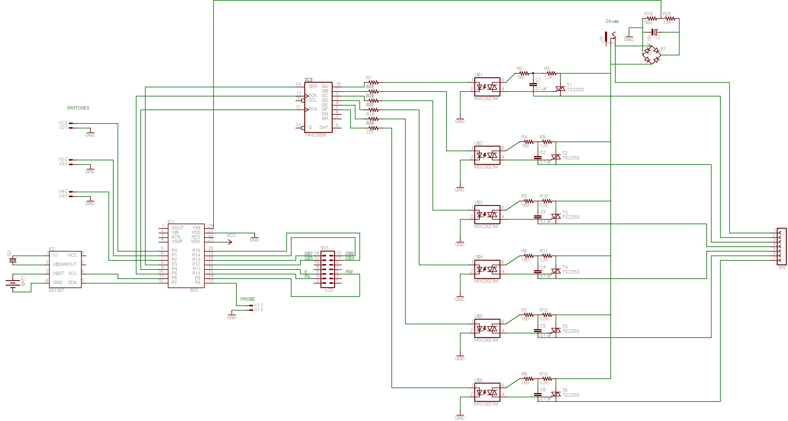
I have attached the circuit diagram if anybody is interested. It's ALMOST finished. Just need to add a few connections to the shift register and I think I'm finally done.
Has anybody else had this kind of problem? How did you solve it? This is my first project so I don't want to do a double sided PCB. Single sided is hurting my brain enough.
However trying to connect up the BS2 pins 12..15 to the LCD header was just impossible (single sided PCB...).
The right hand side of the BS2 looks like this:
P15
P14
P13
P12
...
The LCD header looks like this (rotated 180 degrees to line up better with the BS2):
DB7 DB6
DB5 DB4
. .
. .
E RW
RS .
. .
In the end I just connected the pins on the BS2 to the header in THE ONLY WAY that would eliminate tracks crossing each other. Which was like this:
P15 -> DB4
P14 -> DB6
P13 -> DB7
P12 -> DB5
P11 -> E
P10 -> RS
P9 -> RW
This solves the hardware problem. But software was simple writting nibbles to P12..P15 to drive the LCD. Since the bit ordering is not screwed I have to change my code from this:
LCD_Out:
nLCDbus = yChr.HIGHNIB ' output high nibble
PULSOUT E, 3 ' strobe the Enable line
nLCDbus = yChr.LOWNIB ' output low nibble
PULSOUT E, 3
HIGH RS ' return to character nMode
RETURN
to this:
LCD_Out:
nLCDbus = (yChr.HIGHNIB.BIT0 << 3) | (yChr.HIGHNIB.BIT2 << 2) | (yChr.HIGHNIB.BIT3 << 1) | (yChr.HIGHNIB.BIT1) ' output high nibble
PULSOUT E, 3 ' strobe the Enable line
nLCDbus = (yChr.LOWNIB.BIT0 << 3) | (yChr.LOWNIB.BIT2 << 2) | (yChr.LOWNIB.BIT3 << 1) | (yChr.LOWNIB.BIT1) ' output low nibble
PULSOUT E, 3
HIGH RS ' return to character nMode
RETURN
I have attached the circuit diagram if anybody is interested. It's ALMOST finished. Just need to add a few connections to the shift register and I think I'm finally done.
Has anybody else had this kind of problem? How did you solve it? This is my first project so I don't want to do a double sided PCB. Single sided is hurting my brain enough.
2587 x 1384 - 217K
Comments
Generally speaking trying to correct a hardware problem in software, or a software problem in hardware is not a good idea, unless there is no other workable or cost effective solution. You certainly have another workable and cost effective·solution here, although you may not see it.
All you need to do now is to strighten out the order of the pins with a small cable between the Stamp carrier board, and the LCD. There's more than one reason for using a connecting cable, and no one ever said there had to be a direct Pin 1 ==> Pin 1 correspondence between the cables ends! So, you make yourself a short cross-over cable, something like this, or however you need it wired:
/code
DB4 ---·····
> DB7
········ · \·/
DB6 ----/\
> DB6
······· ·· /··\
DB7 ---·· --\
> DB5
······· ·· /···· \
DB5 ---········
> DB4
E··· ===========> E
RS· ===========> RS
RW· ===========> RW
code/
Now, using a hardware solution, your hardware problem is ended, and you can go back to using the appropriate (software) program coding.
Regards,
Bruce Bates
▔▔▔▔▔▔▔▔▔▔▔▔▔▔▔▔▔▔▔▔▔▔▔▔
<!--StartFragment -->
It's terrific fun though.
▔▔▔▔▔▔▔▔▔▔▔▔▔▔▔▔▔▔▔▔▔▔▔▔
OS-X: because making Unix user-friendly was easier than debugging Windows
That's the only way I know how to keep the spacing and lines intact, and I only know that from seeing others do it that way. It's always worked before, and the message here on the web site looks reasonable, although no ASCII "art" is great!
Apparently Bullwinkle got the idea which is all that really counts. The diagram is useless to anyone else.
Regards,
Bruce Bates
▔▔▔▔▔▔▔▔▔▔▔▔▔▔▔▔▔▔▔▔▔▔▔▔
<!--StartFragment -->
And don't sell yourself short. The diagram isn't necessarily useless to anyone else.
▔▔▔▔▔▔▔▔▔▔▔▔▔▔▔▔▔▔▔▔▔▔▔▔
OS-X: because making Unix user-friendly was easier than debugging Windows
While on the topic of the LCD header. Do I need to run Vcc and/or Vss to the LCD? So far the only signals I am hooking up are E, RW, RS, DB4, DB5, DB6 and DB7.
BTW - The LCD is the parallel one that comes with the Stampworks kit. I probably should use a serial LCD in this project since the parallel unit takes 7 I/O pins. But it's always easier to build with stuff you have on hand. I'd still need the shift register anyway due to the large number of I/O ports this project calls for.
You will certainly need to bring both the positive voltage and ground to the LCD by some means. You may also need a negative voltage, depending on the type of LCD, if the contrast circuit requires it -some do and some don't. If it's convenient to bring it along with the rest of the signals - fine, otherwise you can easily strip down a piece of ribon cable to bring along just what you need for the power circuit.
There are LCD driver IC's which will permit a parallel LCD to be used in serial mode, if you are interested. E-Lab has a couple of different types:
http://www.elabinc.com/
Click on EDE IC's and then on the "LCD Screen Control" IC's
Regards,
Bruce Bates
▔▔▔▔▔▔▔▔▔▔▔▔▔▔▔▔▔▔▔▔▔▔▔▔
<!--StartFragment -->
Does anyone know if Parallax publish the circuit diagram of the Stampworks kit somewhere? That could be useful for me.
http://www.parallax.com/detail.asp?product_id=28138
▔▔▔▔▔▔▔▔▔▔▔▔▔▔▔▔▔▔▔▔▔▔▔▔
Chris Savage
Parallax Tech Support
csavage@parallax.com
Thanks Chris...