

Transistor H-Bridge pulling great deal of current and affecting BS2...
 Steel
Posts: 313
Steel
Posts: 313
This is sort of a run off of my last thread dealing with DC motors, but directly to the point...If you (parallax) could delete my "·Need help with DC motor control··" thread, I would really appreciate it (it veers off topic, and ends.)
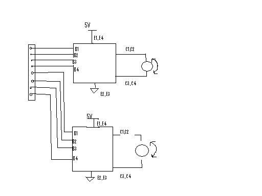
Right now, My BS2 is connected to a 74595 shift register.· That series/parallel register (8 pins) is connected to 2 zetec H-Bridges:
http://www.zetex.com/3.0/pdf/zhb6718.pdf
The H-Bridges are connected to 2 DC motors as in the attached drawing (done so wonderfully in ms paint).
With the H-Bridges attached, the circuit is pulling 250mA and there are odd behaviors in the stamp.· I was under the impression that I connected the H-Bridge Correctly, but it does not seem operational.
Has anybody worked with this H-Bridge?· Did I just mess up on the wiring?
Shaun
512 x 384 - 14K
Comments
· Post Edit -->· I guess I thought the 595s were/are supplying control to the H-bridges?· It's unclear here.· How about getting it all out there?
·
Post Edited (PJ Allen) : 4/18/2006 12:46:25 AM GMT
▔▔▔▔▔▔▔▔▔▔▔▔▔▔▔▔▔▔▔▔▔▔▔▔
Chris Savage
Parallax Tech Support
csavage@parallax.com
The 5V is coming from an external·5V Voltage regulator, which is also giving the BS2 5V.· The·motors and the BS2 are in Parallal from the 5V supply.
Shaun
Post Edit -- I've looked at the XETEX PDF and I'm concerned, since you haven't shown a complete schematic.· You'll need resistors between the STAMP outputs and the H-bridge inputs (unless you're using the HomeWorkBoard, which has built-in limiting resistors), otherwise you're running the outputs raw through a diode (not good.)· Likewise, more so, the outputs of the '595.· Also, you may be coming on in an "illegal" state (with both sides turned on, something like that, which would surely result a high-current state, taking down the STAMP, etc.)· Maybe your drawing is abbreviated, but we could make assumptions all week and never address your trouble.
The PDF pinout shows the device "upside-down", with pins 1 and 8 on the bottom.· Didn't notice that at first, but it's right in my drawing.
hb_nis.jpg is mistake-proof, no illegal state/s possible.· The other is just a schematic for a low-level test (no STAMP used for either.)
One last matter, there are no free-wheeling diodes in parallel with the transistors (internally) and there are none in my schematics (or yours) -- this, too,·can be problematic.
Post Edited (PJ Allen) : 4/19/2006 1:03:01 PM GMT