Automotive Digital Dash Project
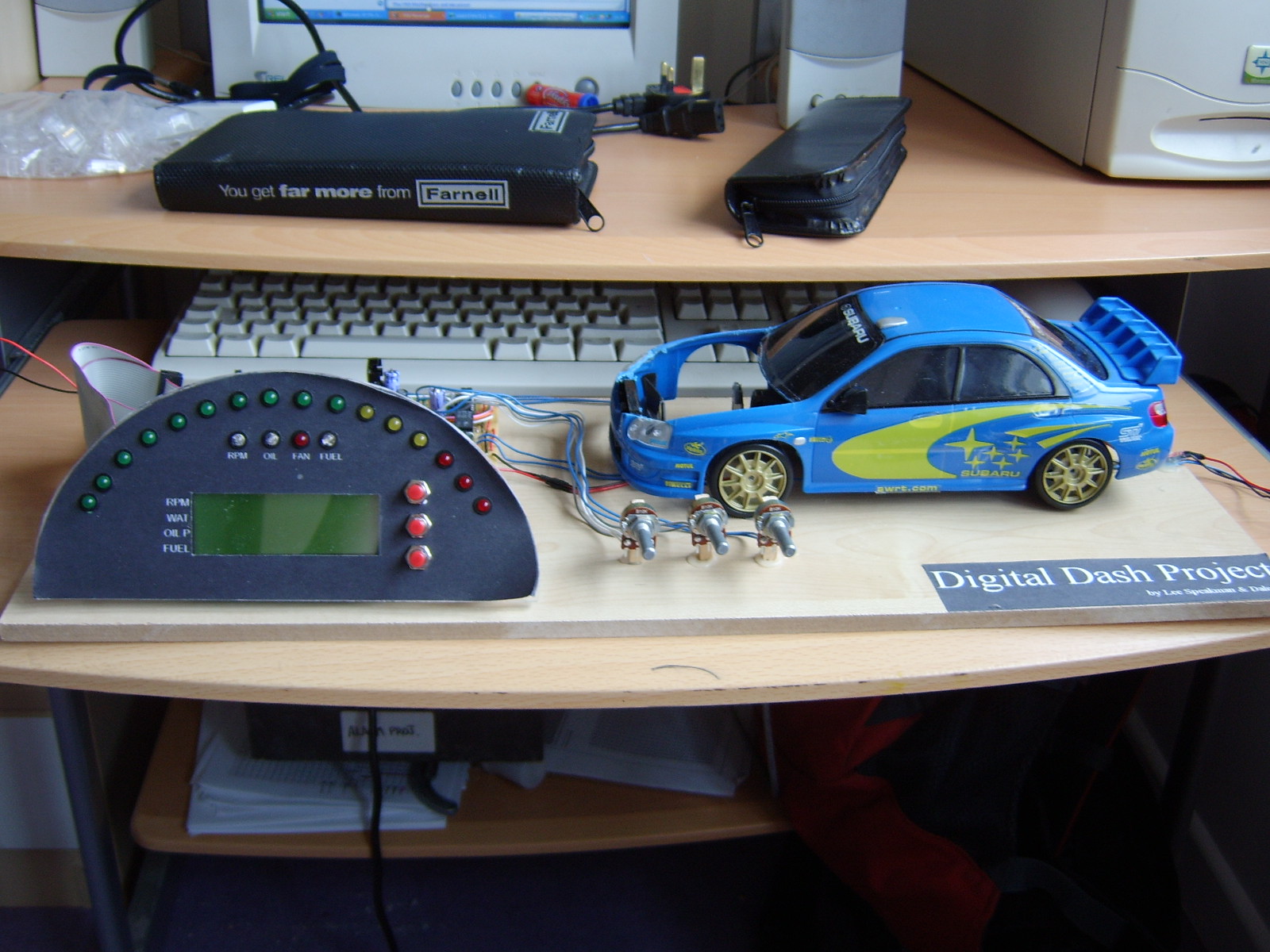
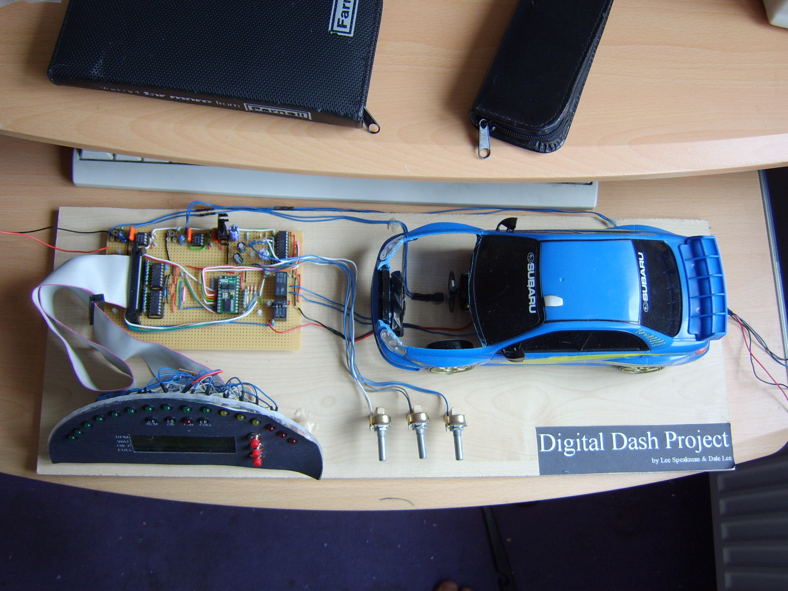
Hi, this is my first time working with a Basic Stamp II and this is my first project. It is a Automotive Digital Dash and It replaces all your analogue instruments with a Digital Display. At the moment I have knocked up a display stand as its part of my university project. The rear wheel speed and engine motors are inside the car and can be controlled by seperate voltage sources.
The POT's on the front simulate the changes in voltages produced by the fuel, oil pressure and water temperature transducers.
The dash has many user programmable features such as RPM Limiter, which will stop you over reving your engine as well as a launch control function that will hold the RPM at a set level when you press the centre button. You can also set at what point you want the engine fan to come on, low fuel levels and oil pressure warning etc.
Theory of operation:
2 LM2917's are used for sensing wheel speed and engine speed. The frequency of a rotating wheel or (sparks in the case of the engine) are turned into a voltage. The voltages from this and the other transducers are fed into an 8 Channel ADC and are multiplexed into the Stamp.
The stamp does some math and returns your roadspeed, RPM and all other information to the LCD. The Lights at the top are rev lights, these are scaled according to your maximum RPM.
All seems fairly simple in hindsight, but it was quite difficult getting to this stage.
My only gripes so far is Id like to make the code a little more efficient so the screen can refresh quicker, and im getting some fluctuations of road speed and RPM. I assume this is because of the ripple voltage produced by the LM2917's. If anyone can suggest how to reduce this I would be very thankful !


Comments
▔▔▔▔▔▔▔▔▔▔▔▔▔▔▔▔▔▔▔▔▔▔▔▔
- Stephen
·· Back when you were first working on this, I thought you had added a degree symbol to the LCD temp display?· I don't see it in the picture though.
▔▔▔▔▔▔▔▔▔▔▔▔▔▔▔▔▔▔▔▔▔▔▔▔
Chris Savage
Parallax Tech Support
csavage@parallax.com
Once if done my exams Im going to start fresh with it.
Chris, I do, thats an old snapshot as I forgot to take a picture of the unit with the screen on!