open loop project
 jlac
Posts: 1
jlac
Posts: 1
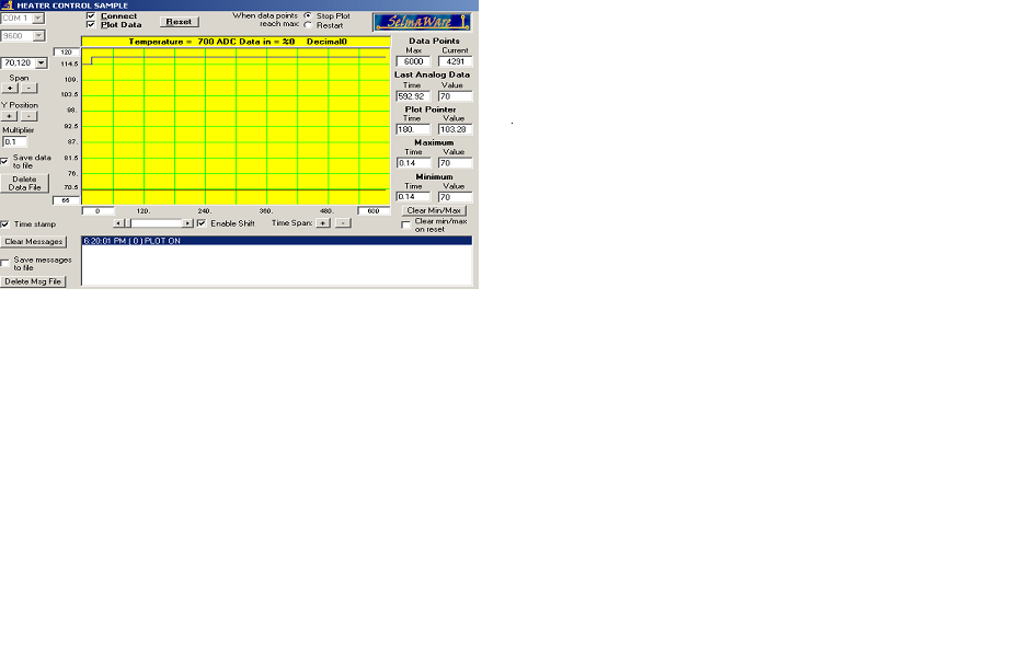
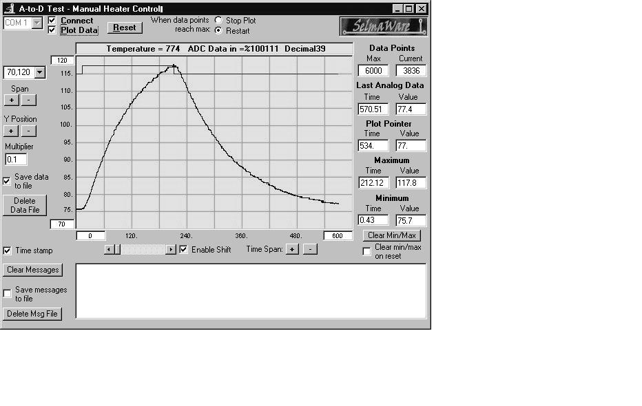
Hi my name is jose, and currently i'm taking a control class; i'm having difficulty whenever i load up this code up, the stamp2 would lock in 0 or 255 whenever displaye in spl; i'm trying to attain figure 4.4 pg 106 in the continous process control (exp #4) "Industrial control by marty hebel and will Devenport"; i've trouble shooted the hardware and practically replaced everything even the code; i do not believe the problem is the writing of the code but something that escapes my wit. i've posted the attachmetn in hope that someone may know what how to solve this predicament; also, i've attached the graph that i keep getting and the one how is suppose to be.
' {$STAMP BS2}
' {$PBASIC 2.0}
'Program 4.1: Analog-to-Digital & ON-OFF test with StampPlot Interface
'Pushbutton P1 toggles the heater fully ON and OFF. It then establishes
'constants and variables used to acquire data from the ADC0831 serial A-to-D. 'StampPlot is
'used TO graphically display results. Program assumes that the 'circuitry is set according to
'Figure 4.3. ADC0831: "chip select" CS = P3, "clock" 'Clk=P4, & serial 'data output"Dout=P5.
'Zero AND Span pins: Digital 0 = Vin(-) = '.70V and Span = Vref = .50V.
'Configure Plot
PAUSE 500 ' Allow buffer to clear
DEBUG "!RSET",CR ' Reset plot to clear data
DEBUG "!TITL HEATER CONTROL SAMPLE",CR 'Caption form
DEBUG "!PNTS 6000",CR ' 6000 sample data points
DEBUG "!TMAX 600",CR ' Max 600 seconds
DEBUG "!SPAN 70,120",CR ' 70-120 degrees
DEBUG "!AMUL .1",CR ' Multiply data by .1
DEBUG "!DELD",CR ' Delete Data File
DEBUG "!SAVD ON",CR ' Save Data
DEBUG "!TSMP ON",CR ' Time Stamp On
DEBUG "!CLMM",CR ' Clear Min/Max
DEBUG "!CLRM",CR ' Clear Messages
DEBUG "PLOT ON",CR
DEBUG "!RESET",CR
' Define constants & variables
CS CON 3 ' 0831 chip select active low from BS2 (P3)
CLK CON 4 ' Clock pulse from BS2 (P4) to 0831
Dout CON 5 ' Serial data output from 0831 to BS2 (P5)
Datain VAR Byte ' Variable to hold incoming number (0 to 255)
Temp VAR Word ' Hold the converted value representing temp
TempSpan VAR Word ' Full Scale input span in tenths of degrees.
TempSpan = 5000 ' Declare span. Set Vref to .50V and
' 0 to 255 res. will be spread over 50
' (hundredths).
Offset VAR Word ' Minimum temp. @Offset, ADC = 0
Offset = 700
' Declare zero Temp. Set Vin(-) to .7 and
' Offset will be 700 tenths degrees. At these
' settings, ADC output will be 0-255 for temps
' of 700 to 1200 tenths of degrees.
Wkspace1 VAR Byte ' Workspace for the PB1's BUTTON command
Wkspace1 = 0 ' Clear the workspace before using BUTTON
LOW 8 ' Initialize heater OFF
Main:
'Experiment #4: Continuous Process Control
'Page 106 • Industrial Control Version 1.1
GOSUB Getdata
GOSUB Calc_Temp
GOSUB Control
GOSUB Display
GOTO Main
Getdata: ' Acquire conversion from 0831
LOW CS ' Select the chip
LOW CLK ' Ready the clock line.
PULSOUT CLK,10 ' Send a 10 uS clock pulse to the 0831
SHIFTIN Dout, CLK, MSBPOST,[noparse][[/noparse]Datain\8] ' Shift in data
HIGH CS ' Stop conversion
RETURN
Calc_Temp: ' Convert digital value to
Temp = TempSpan/255 * Datain/10 + Offset ' temp based on Span &
RETURN ' Offset variables.
Control: ' Manual heater control
BUTTON 1,1,255,0,Wkspace1,1,Toggle_it
RETURN
Toggle_it:
TOGGLE 8
RETURN
Display: ' Plot Temp, binary ADC, & Temp status
DEBUG DEC Temp,CR
DEBUG IBIN OUT8,CR
DEBUG "!USRS Temperature = ", DEC Temp," ADC Data in = %", BIN Datain, " Decimal",DEC Datain, CR
RETURN