

Basic Stamp questions from a Newbie...
 ScottishCaptain
Posts: 10
ScottishCaptain
Posts: 10
Greetings to all!
I'm sort of new to this whole Microcontroller thing, so I've got a few questions that I can't seem to get a 100% answer from the piles of documentation I've been sorting through.
If anyone could help me out here, it would be greatly appreciated.
I'd like to build myself a really suped-up Sumovore robot from the guys over at Solarbotics, but despite piling over a ton of documentation, I can't seem to find 100% definitive answers on some of this stuff (Solarbotics basically said "Try it, let us know if it works"). I *really* don't want to fry anything, in particular a Javelin or a PLED module (expensive stuff).
So here are my questions.
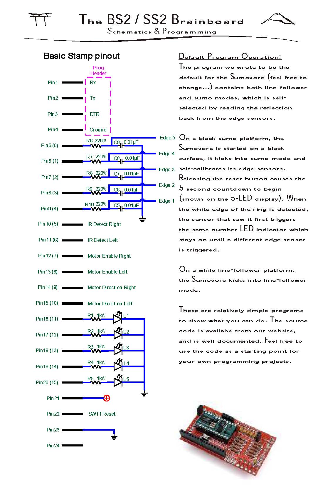
First - As shown on the attached Jpg page from the Sumovore Brainboard/BS2 addon module, it shows the layout of the 24 Pin Socket. Everything seems OK for a Javelin Stamp Module, except Pins 5-9, for reading in the analog value of the IR Sensors (for line following).
Solarbotics is using RCTime in their sample code. The Javelin manual states an example circuit *similar*, but not *excat* to the one Solarbotics is using here.
Edge 5 to Edge 1 are the actual sensors on another PCB.
Will this setup on the Solarbotics PCB for Pins 5-9 work with a Javelin stamp using its own RCTime command?
Second - I want to hook up another Stamp (BS2 Equivalent, just in another form factor) to the Javelin using the Solarbotics Brainboard (see attached).
The only pins available to psuedo-use are pins 16 to 20. These have a 1kOhm Resistor and LED's hanging off them, with the LED being tied to ground. Presumably the Stamp can use these to light 'em up with HIGH or LOW on the appropriete pin.
The LED's should draw around 5mA each.
I'd like to hook the second Basic Stamp up to Pins 16-20 directly, ie, nothing but wire inbetween the 2nd BS2 and the Javelin. Each line however, has the LED and Resistor hanging off to ground.
Will this work for simple SERIN/SEROUT communication on dedicated lines between the Stamp's? At worst, I'd think the resistor and LED would act as a Pulldown for each line, and the LED's would blink with the passing of data between the Stamp's.
I wanted to set it up as follows:
Pin 16 - SERIN on BS2, SEROUT for Javelin
Pin 17 - SEROUT on BS2, SERIN for Javelin
Pin 18 - Attention for BS2
Pin 19 - Attention for Javelin
Pin 20 - NC (except for the Pin 20 LED and Resistor)
Each stamp does a HIGH on its attention line to get the attention of the other Stamp, and then transmits on the appropriete pin using SEROUT (while the other unit uses SERIN). When they are done, the Attention line goes low.
Will this work, for communication between Stamp's, with the LED's & Resistors hanging off each line? Or will this fry something?
Third - I want to stick a Matrix Orbital PLED module (2x16) Display on the robot, connected up to the BS2 (not the Javelin).
Matrix Orb says that I can kick the display into RS232 TTL mode easily enough. They do not mention Pullup/Pulldown resistors when connecting the RS232 TTL's TX and RX lines directly to the Basic Stamp.
Is this the case for SERIN and SEROUT? Can the Matrix Orbital RS232 TTL lines be connected directly to, lets say P0 and P1?
Those are my questions, any help would be great. This may be simple stuff, but I'm not completly convinced I kow what I'm doing yet, so I don't want to risk blowing anything (although, I've been building BEAM robots for years, just not Basic Stamp powered stuff or anything RS232ish).
If anyone is wondering, I plan to use the BS2 to handle the MO PLED Display and a Memsic Accelerometer (to record impacts at a specific angle), since the Javelin has its pins tied up with the robot, and the only thing I can think of is to use SERIN and SEROUT between the BS2 and Javelin to send simplified serial commands to the BS2 (and visa versa).
Cheers!
Keven Tipping
I'm sort of new to this whole Microcontroller thing, so I've got a few questions that I can't seem to get a 100% answer from the piles of documentation I've been sorting through.
If anyone could help me out here, it would be greatly appreciated.
I'd like to build myself a really suped-up Sumovore robot from the guys over at Solarbotics, but despite piling over a ton of documentation, I can't seem to find 100% definitive answers on some of this stuff (Solarbotics basically said "Try it, let us know if it works"). I *really* don't want to fry anything, in particular a Javelin or a PLED module (expensive stuff).
So here are my questions.
First - As shown on the attached Jpg page from the Sumovore Brainboard/BS2 addon module, it shows the layout of the 24 Pin Socket. Everything seems OK for a Javelin Stamp Module, except Pins 5-9, for reading in the analog value of the IR Sensors (for line following).
Solarbotics is using RCTime in their sample code. The Javelin manual states an example circuit *similar*, but not *excat* to the one Solarbotics is using here.
Edge 5 to Edge 1 are the actual sensors on another PCB.
Will this setup on the Solarbotics PCB for Pins 5-9 work with a Javelin stamp using its own RCTime command?
Second - I want to hook up another Stamp (BS2 Equivalent, just in another form factor) to the Javelin using the Solarbotics Brainboard (see attached).
The only pins available to psuedo-use are pins 16 to 20. These have a 1kOhm Resistor and LED's hanging off them, with the LED being tied to ground. Presumably the Stamp can use these to light 'em up with HIGH or LOW on the appropriete pin.
The LED's should draw around 5mA each.
I'd like to hook the second Basic Stamp up to Pins 16-20 directly, ie, nothing but wire inbetween the 2nd BS2 and the Javelin. Each line however, has the LED and Resistor hanging off to ground.
Will this work for simple SERIN/SEROUT communication on dedicated lines between the Stamp's? At worst, I'd think the resistor and LED would act as a Pulldown for each line, and the LED's would blink with the passing of data between the Stamp's.
I wanted to set it up as follows:
Pin 16 - SERIN on BS2, SEROUT for Javelin
Pin 17 - SEROUT on BS2, SERIN for Javelin
Pin 18 - Attention for BS2
Pin 19 - Attention for Javelin
Pin 20 - NC (except for the Pin 20 LED and Resistor)
Each stamp does a HIGH on its attention line to get the attention of the other Stamp, and then transmits on the appropriete pin using SEROUT (while the other unit uses SERIN). When they are done, the Attention line goes low.
Will this work, for communication between Stamp's, with the LED's & Resistors hanging off each line? Or will this fry something?
Third - I want to stick a Matrix Orbital PLED module (2x16) Display on the robot, connected up to the BS2 (not the Javelin).
Matrix Orb says that I can kick the display into RS232 TTL mode easily enough. They do not mention Pullup/Pulldown resistors when connecting the RS232 TTL's TX and RX lines directly to the Basic Stamp.
Is this the case for SERIN and SEROUT? Can the Matrix Orbital RS232 TTL lines be connected directly to, lets say P0 and P1?
Those are my questions, any help would be great. This may be simple stuff, but I'm not completly convinced I kow what I'm doing yet, so I don't want to risk blowing anything (although, I've been building BEAM robots for years, just not Basic Stamp powered stuff or anything RS232ish).
If anyone is wondering, I plan to use the BS2 to handle the MO PLED Display and a Memsic Accelerometer (to record impacts at a specific angle), since the Javelin has its pins tied up with the robot, and the only thing I can think of is to use SERIN and SEROUT between the BS2 and Javelin to send simplified serial commands to the BS2 (and visa versa).
Cheers!
Keven Tipping
1100 x 1700 - 169K