

Are you looking for more PROGRAM space?
 KC8DKT
Posts: 76
KC8DKT
Posts: 76
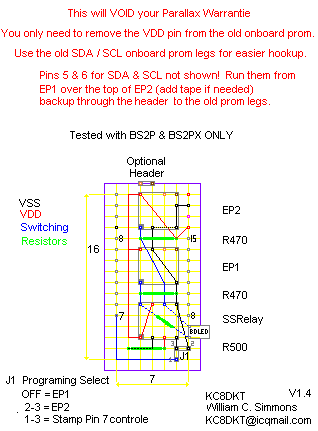
THIS WILL VOID YOUR PARALLAX WARRANTIE
This was tested on the BS2P24 & BS2PX only but with the right EProms SHOULD work on them all.
This is an easy Perf / DIP mod to add 2 EPRoms for 16 PROGRAM slots that anyone with basic skills can do.
If you can live with the slower OEM DIP stamps or you have the skills to work with SMDs you should do it.
You only need to remove the VDD from the old OnBoard EPRom for this mod. You can then use the legs for an eaier SDA / SCL hookup.
I will try to answer questions but I got this working with lots of testing not smarts.
Parts List
1x Solderable Perf. Board 16x7 matrix with 0.1" spacing
···················· Allelectronics.com·········· PC-4···························· $2.00
2xEPRoms ( Remove Legs 2,3, & 7 )
···················· Digikey.com··················· 24FC128-I/P-ND············· $1.80
·1 SSRelay
····················· Allelectronics.com·········· LAA110························ $2.75
····················· Digikey.com··················· CLA103-ND··················· $5.23
1 BiPolar Led ( Optional ) No led will save Batt. life.
······················ Allelectronics.com············ LED-6···················· $0.50
2x Resistors 470 ( EPRom 1 & 2 )
1x Resistor 500 ( SSRelay )
1x Resistor for the led ( Optional if no led )
······················· The higher the better for Batt. life but the dimmer the Led will be
························ Too low and the EPRoms will not have enough power.
8x High Prec. snap sockets ( with some extras )
························ Allelectronics.com·················· SIP-81············ $0.20
Any small stranded ( smaller the better ) wire you can pull apart can be used for the traces.
2x6 pin headers snapable
1 jumper header
1 jumper conector for the SDA / SCL·· ( Optional )
Test your board on the I2C of pins 0/1 or 8/9 BEFORE you mod the old OnBoard EPRom!
You should check the Pin 7 lead ma when sinked as well.
Shorts anywhere on the board may damage the relay or EPRoms but only Pin Lead 7 and
the SDA / SCL leads can damage your stamp.
If your up for some real fun use a MCP23016 for the switching.
Thats 16 EProms you can switch with only 1 I2C command.·

I have tested up to·6 with Np.
Too get more then 3 EPRoms working you will have to REMOVE the old
OnBoard EPRom though. Even with the VDD removed the chip still pulls
some power from the SDA / SCL.
Post Edited (KC8DKT) : 4/4/2006 3:20:34 AM GMT

Comments
In that case I would suggest that you make d@mn sure that you have the EXACT same program in SLOT0 on both EEPROMs, or you have no way of knowing what the BS2p will do when you switch from one EEPROM to another.
For those who wants to have even more space, I would rather suggest using a 74138 3-to-8 decoder chip and connect the 3 input pins to I/O-pins on the BS2e/sx/p/pe/px and the 8 outputs to separate CS-pins on up to 8 different EEPROMs...
Even with the limit of having the same program in SLOT0 on all 8 EEPROMs, you still have 56 2KB program slots, and in the case of the BS2pe(if you use the correct EEPROM), 56 Program SLOTs, and 64 DATA slots...
This metod doesn't use I2C, though, so works on ALL multibank BS2s, not just the BS2p/pe/px models.
(They are the ones which support I2C natively.)
Of course, my method will also void any warranty...
And no, I haven't actually tried it...
▔▔▔▔▔▔▔▔▔▔▔▔▔▔▔▔▔▔▔▔▔▔▔▔
Don't visit my new website...
If you had tested the switching of the SDA / SCL lines from EP1 over to EP2 you would have found that after about 40min the stamp would lockup or start resetting!
If this layout was intended for more then 2 eproms I wouldn't have pointed out that you have to remove the old eprom to add more.
As I said, endless testing got this working not smarts on my part. So I do look forward to feedback on what others have tryed or new ideas to test.
That SHOULD work, but as the BS2 always boots to SLOT0 after a reset, I figured that would be the common-sense choice. (I'm willing to listen to any argument you have for using that slot, though)
With 'CS' I meant 'Chip Select' lines, NOT the Serial Clock or Data lines.
(Pin 1, also known as A0 IS a Chip Select type pin)
Switching the SCA/SCL lines with relays probably introduced 'noise' on the system, and as the BS2 then tries to interpet it as PBASIC tokens...
Using a relay for this application is not a good choice as you are forced to have resistors to tie the pins to VSS when the chip is not selected. (A 74138 or any other chip would remove that need. In fact, this is the kind of tasks the chip was designed for)
Yes, it works, but... It's just so... not elegant... And mixing logic and 'non-logic' circuits like that is a bad design-habit.
Also, a 74hc138 is $.45 at Digi-key...
The MCP23016 you mention, though, is a good idea.
(Though it, too, would need bit-banging to work on a BS2e and BS2sx as they don't have I2C commands)
▔▔▔▔▔▔▔▔▔▔▔▔▔▔▔▔▔▔▔▔▔▔▔▔
Don't visit my new website...
The following information comes solely from my reccolections of a bunch of messaging that went on many years ago. I apologize if any part of it isn't 100% accuracte. I will try to find the original posts, but make no guarantees.
A similar concept was attempted shortly after the BS-2SX was announced. It worked too, as you have found out. I suspect, in the long run, you may have the same seemingly insurmountable problem that the other gent did, and that was with long term reliability.
Time and time again this other system would work flawlessly, but once or twice a week in hard-use operation (beta testing), all of a sudden the entire system would hang. The electro-mechanical relay was the first to catch the "blame" as it was presumed to be putting noise on the lines, and it was replaced (as I remember) with some solid state cross-point switches, not unlike these, or something like them:
http://www.maxim-ic.com/quick_view2.cfm/qv_pk/4314
Since these are designed as analog devices, there was eventually some sort of interfacing problem using them, although I don't remember what it was. Next came a solid state relay, but I honestly don't remember the problems encounted there. All I do remember is that the project was eventiually scrapped as a great concept, but not sufficiently reliable to be used in the field, especially since it voided the Parallax warranty.
I hope you make out better than that fellow did, and find your multi-EEPROM system to be exceedingly reliable.
Regards,
Bruce Bates
▔▔▔▔▔▔▔▔▔▔▔▔▔▔▔▔▔▔▔▔▔▔▔▔
<!--StartFragment -->
EP1 Startup in Slot 0
EP1 run slots 1 - 7
EP1 at the end of slot 7 you would need to run 0 to get back to the swiching code
EP1 - If startup stay in EP1
If EP1 is done then switch to EP2
Thats alot more work then needed but yes, it could be done that way I THINK
RGR on the CS, I was thinking you ment the SDA line.
As for the SSRelay,
TTL/SMOS inputs
Its optically isolated
It only need 1 pin and a High/Low witch all stamps can do
It fits under the stamp for the PiggyBack board so it will still work with all the Parallax boards.
The only thing I use on my SMD setup that is used here is the A0 switching. I did this PiggyBack setup for posting in this forum only and used DIPs so everyone with basic skills could do it.
There is always some one asking how to get more program space.
I replaced the DigSwitchs with the Opto Relay and fixed the buffer data problem
Going with the A0 instead of the SCL / SDA / W-R Pins fixed the Reset, Restart, and LockUp problems
My BS2P24 has bean going for about 4 weeks now with the A0 setup doing Reads / Wrights and checking it with SPRam. Each loop saves to the next EPRom location so it does not wear it out.
If you only remove the VDD line like I said it is easy to go back to the stock setup if you have a problem.
I like your idea about the 3-> decoder, but, what about rearranging the address lines of the existing prom to be under the stamps control? Now, all the noise and flabbla about switching is gone... Yes, custom code will needed to access / switch / control, but still, at that rate... that would add quite a few more banks.
Well, thats my idea... [noparse]:)[/noparse]
▔▔▔▔▔▔▔▔▔▔▔▔▔▔▔▔▔▔▔▔▔▔▔▔
Just tossing my two bits worth into the bit bucket
KK
·
Building a new board to hold 2 stamps just so I could have the program space for my new color LCD would have sucked. I spent about a week working with my old BS2P24 before I found a way that did not lockup or reset. You can get this to work countless ways in the short turm though. So test, test, test before you say your done!
All in all this was alot more FUN then etching out a new board and power setup. One thing that turned me on to this LCD was the I2C interface so I could add it without any problems. I guess that "no problems" part did not go so well but it was still fun and it all still fits in the PC case mounts. Now if only I can get this touchscreen working a bit better.
There may be other problems, too, but I won't be able to look at the until this weekend. (The boss insists that I at least pretend to do some work at the office... Grumpy fella)
▔▔▔▔▔▔▔▔▔▔▔▔▔▔▔▔▔▔▔▔▔▔▔▔
Don't visit my new website...
Gadgetman, well, 4 eeproms are better then 1...
▔▔▔▔▔▔▔▔▔▔▔▔▔▔▔▔▔▔▔▔▔▔▔▔
Just tossing my two bits worth into the bit bucket
KK
·
Only 4 chips is ~500k!
When you export txt and DATA to EPRom or NVRam 128k is ALOT of program space to fill up!
I only use chip 1 and 3 slots in chip 2 and chip 3 is more or less blank.
The 2P24 has a working 6 chip setup but the 8 chip setup is still locking up from time to time. 6 MAY be the max without floating the SDA lines in a bank setup. Keep in mind that getting more then 3 to work is just for fun!
BTW, Does anyone know where I can get some ram thats 8x16 with I2C? I can not find any on Digikey. Since Prom and Ram use the same 1010 I2C ID it would be fun to try a NVRam setup.