

Driving a Network of SX's
 Amit
Posts: 27
Amit
Posts: 27
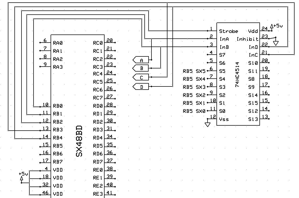
I am planning to have 16 slave SX's running together and trading data with a master SX.· Each SX would be on a separate PBC.· In order to request data from a particular SX without affecting the other SX's, I have a bus running inbetween all the boards.··4 lines of this bus are dedicated to IDing the target SX 2^4=16.· These 4 lines are fed into a decoder.· The decoder then drives the appropiate pin high.·
Example:··The master sends out in the format [noparse][[/noparse]Line D, Line C, Line B, Line A].··If the master sends out [noparse][[/noparse]1,0,1,1] then the decoder sends line S11 high.· S11 is connected to RB5 on SX #11 and causes an interrupt.· (This last connection is done by hand ie: not a trace on the board)
Each SX has its own decoder.· Every SX and decoder is connected to the 4 line ID bus.· For example:··On each board RB1 connects to InA on the decoder but also connects to every other RB1 and InA.·
Only the master unit wil be outputting on Line A-D.· The other SX's are connected to those lines only to make the fabrication of the boards as cheap as possible.· Will it be a problem for one SX pin to drive 16 other SX pins as well as 16 decoder pins.· The decoder datasheet says the input current is 1uA max.· If all the slave pins are put to input mode will I run into a problem?· Would I be much better off just wiring the master SX to the decoder by hand and just leave the slave SX pins un connected?
I hope I explained this clearly enough.· If not let me know.· I have attached a simplified schematic help.
1141 x 758 - 113K
Comments
Why not use a 2-wire bus that interconnects all sx's?
This bus could be I2C or half duplex serial.
regards peter
·
The master SX acts as I2C bus master, and all other SXes act as I2C slaves each reading and decoding the device-IDs sent from the master with each command, reacting on their unique device-ID only.
With any kind of bus, the line lengths may be a concern. You did not mention how far apart the 16 slaves are. By definition, the I²C bus is primarily intended to interconnect ICs on one PCB, or maybe several PCBs located close together. To my own experience, I could extend an I²C bus across several meters with a transfer rate of 25 kbps. If this is fast enough for your application, you might give it a tray.
▔▔▔▔▔▔▔▔▔▔▔▔▔▔▔▔▔▔▔▔▔▔▔▔
Greetings from Germany,
Günther
TI SN75176, about $0.75 US each (PDIP8) also avail in other formats. I've been having fun playing with these things. Discovered them through Jan Axelson's book "Serial Port Complete" (if you don't have this book you should get it).
Datasheet: http://focus.ti.com/lit/ds/symlink/sn75176b.pdf
▔▔▔▔▔▔▔▔▔▔▔▔▔▔▔▔▔▔▔▔▔▔▔▔
John J. Couture
San Diego Miramar College