

Oscilloscope & I2C
 Earl Foster
Posts: 185
Earl Foster
Posts: 185
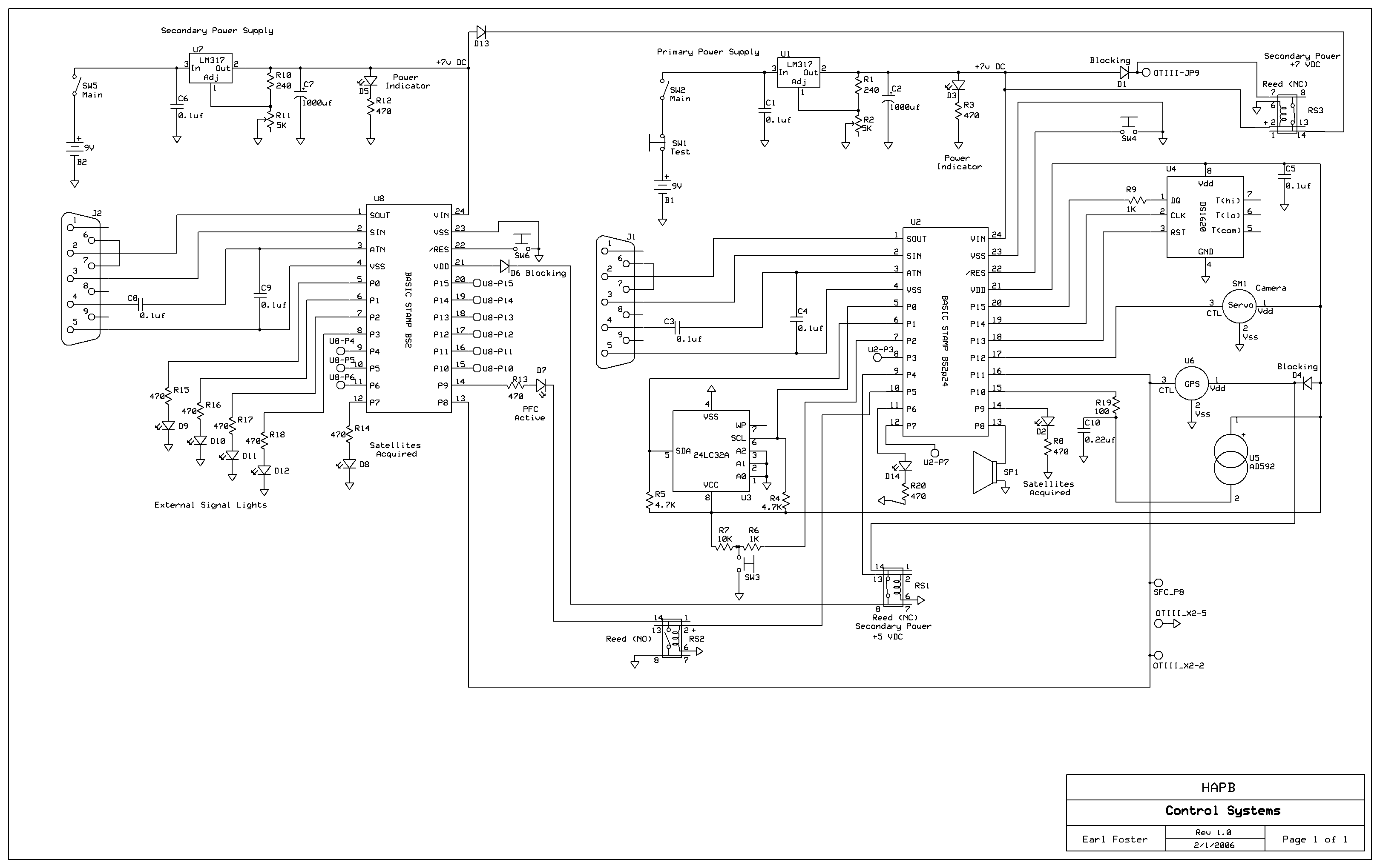
I am writing and reading data to a 24LC32 using the I2C command.·· My breadboard layout works perfect.· My PCB layout does not.· I have checked the wiring against the schematic many times and I can’t find any issues.· I have done continuity and voltage checks against the 2 circuits and they are the same. ·
·
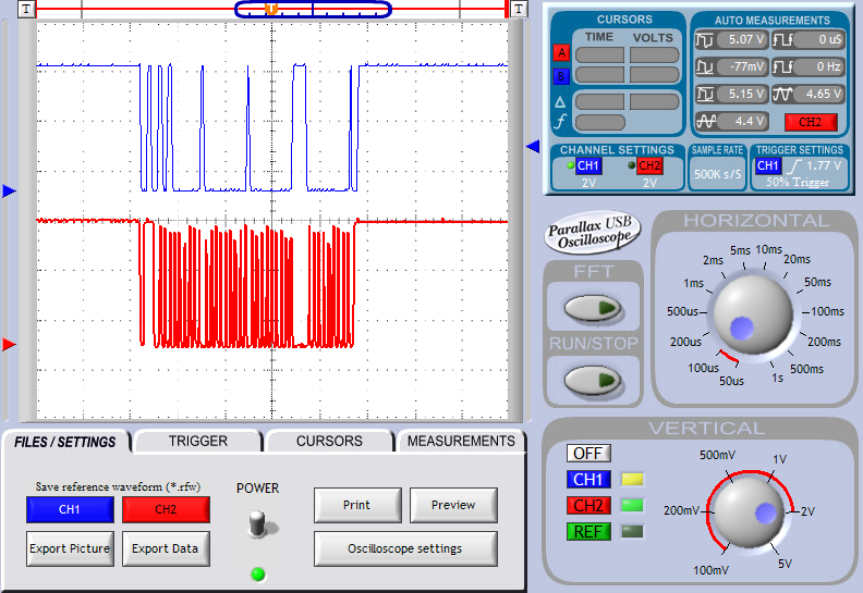
So now I am running the O-scope against the circuit and they are different but even the working circuit doesn’t look the way I expected.· I was expecting something along the lines of the Phillips I2C documentation graphs so I figure I must be doing something wrong.· I have attached an I2COUT trace with my settings and ran·code 24LC32.bsp to capture the read statement. ·The blue trace is data and the red trace is clock.
·
I am looking for guidance so I can properly troubleshoot this circuit with the O-Scope.·
Thanks
·
So now I am running the O-scope against the circuit and they are different but even the working circuit doesn’t look the way I expected.· I was expecting something along the lines of the Phillips I2C documentation graphs so I figure I must be doing something wrong.· I have attached an I2COUT trace with my settings and ran·code 24LC32.bsp to capture the read statement. ·The blue trace is data and the red trace is clock.
·
I am looking for guidance so I can properly troubleshoot this circuit with the O-Scope.·
Thanks
Comments
·· What exactly is happening with your EEPROM?· What results are you getting?· One thing I see in your schematic is your WP line is floating.· Now this may not be an issue, but I would think you would want it tied LOW if you're not using it.· I wonder if the line is floating and possibly causing problems.
▔▔▔▔▔▔▔▔▔▔▔▔▔▔▔▔▔▔▔▔▔▔▔▔
Chris Savage
Parallax Tech Support
csavage@parallax.com
·· Good catch, I hadn't noticed that until you mentioned it.· It begs the question though, how did this work on the breadboard?· Perhaps everything wasn't connected there?· In any event that is correct.· There will not be enough power from the BS2p VDD pin to run these items.· In fact you should really try to avoid using this pin at all in most cases.·
▔▔▔▔▔▔▔▔▔▔▔▔▔▔▔▔▔▔▔▔▔▔▔▔
Chris Savage
Parallax Tech Support
csavage@parallax.com
Turning back to my current issus the only piece I am having a problem with on the PCB is the 24LC32. In order to troubleshoot the 24LC32 all other components have been removed from the PCB so I could isolate that circuit. So I am still looking for some suggestions on what else I can do to troubleshoot the problem. I am thinking a comparsion between the working and non-working circuit but I need a good baseline of the working circuit and as I said I don't think I output I have is correct.
So I guess what I am asking is if you were going to monitor communications between the Stamp and the 24LC32 using the I2CIN and I2COUT statement during a read and write cycle what settings and probe connections on the Parallax O-Scope would provide me the best results?
·· You would monitor the SDA and SCL lines using the two channels.· You would connect ground to VSS.· It also appears as though you're connecting the two VDD supplies from each Stamp Module through a Reed Relay?· I guess the main point I wanted to get across to you in that a servo alone draws more than the on-board regulator can provide.· We would never recommend using that for just the servo, but then you have the other circuitry.· If it was just the DS1620 and the 24LC32 then that would probably be okay.· I guess I would also recommend tying WP low to see if it helps.
▔▔▔▔▔▔▔▔▔▔▔▔▔▔▔▔▔▔▔▔▔▔▔▔
Chris Savage
Parallax Tech Support
csavage@parallax.com
Getting back the O-scope. That is how I connected the probes but it doesn't look right and I am thinking that my timing is off and I can't get over how much noise there is in the trace. Currently it is set to 100us with a 2 volt division. Perhaps I can need to adjust the timing or write a new program that will generate a single read and write and capture that trace.
Well I will work on that tonight.
·· Are you using the same power supply in both systems?· Also, there is something else to consider here.· I have been designing and building circuits for many years, and one thing I learned early on is that breadboards have some capacitance which can eliminate some noise in a system.· I didn't see any .1uF capacitors in your schematic and I can't help but wonder if you're experiencing noise on the lines.
▔▔▔▔▔▔▔▔▔▔▔▔▔▔▔▔▔▔▔▔▔▔▔▔
Chris Savage
Parallax Tech Support
csavage@parallax.com
kelvin
·· Kelvin is correct.· On the BS2p when using the I2CIN/I2COUT commands the root pin (Which must be P0 or P8) must be connected to SDA.· The next highest pin is automatically SCL.
▔▔▔▔▔▔▔▔▔▔▔▔▔▔▔▔▔▔▔▔▔▔▔▔
Chris Savage
Parallax Tech Support
csavage@parallax.com
I just finished making the swap and it works like a champ·
Post Edited (Earl) : 3/21/2006 11:28:40 PM GMT