Shop OBEX P1 Docs P2 Docs Learn Events
What's wrong — Parallax Forums

What's wrong

xaer8xaer8 Posts: 15
edited 2006-03-17 15:17 in BASIC Stamp
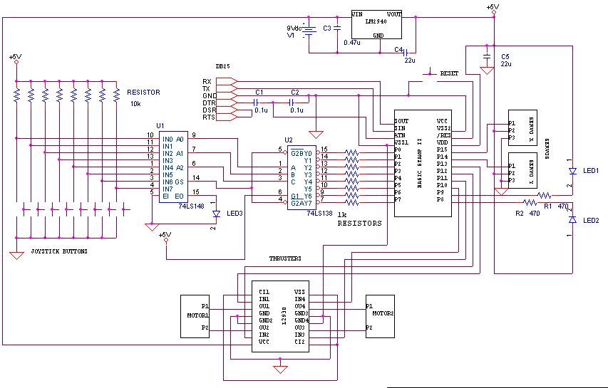
I'm in progress of completing my first·mini robot (for my degree final year project!). I've construct my own circuit, rather than buying an already complete robot kit. I've connect the·BS2 just like the way·in this schematic i made.·The problem is when i connect the·BS2 with my PC using serial cable, they indicated, echo-yes, loopback-no, and no indication of version and no device type·in COM3. Even when i tried to run any program to my BS2, it indicates "no basic stamps found". Is the problem at my serial com circuit or at my BS2 hardware connection? Please help me with this...

▔▔▔▔▔▔▔▔▔▔▔▔▔▔▔▔▔▔▔▔▔▔▔▔
Let's try our best together!
853 x 545 - 74K
new.JPG 74.3K

Comments

  • Jon WilliamsJon Williams Posts: 6,491
    edited 2006-03-14 20:25
    Check the easy stuff first: do you have power to the BASIC Stamp? (check with a meter, don't go by the schematic)

    ▔▔▔▔▔▔▔▔▔▔▔▔▔▔▔▔▔▔▔▔▔▔▔▔
    Jon Williams
    Applications Engineer, Parallax
  • dechief micheldechief michel Posts: 75
    edited 2006-03-14 20:34
    Did your led blinkink, if yes you have power on to your bs.
    Why are you looking for com 3?
    Maybe you use a usb to com interface and than you have to check the right port(check into your material com availaible)
    Greatings from Belgium,
    Michel
  • xaer8xaer8 Posts: 15
    edited 2006-03-14 20:34
    Yes. 4.95V at VDD (pin 21)

    ▔▔▔▔▔▔▔▔▔▔▔▔▔▔▔▔▔▔▔▔▔▔▔▔
    Let's try our best together!
  • xaer8xaer8 Posts: 15
    edited 2006-03-14 20:38
    Only com3 responded. Other com's indicated 'invalid port'.

    ▔▔▔▔▔▔▔▔▔▔▔▔▔▔▔▔▔▔▔▔▔▔▔▔
    Let's try our best together!
  • dechief micheldechief michel Posts: 75
    edited 2006-03-14 20:44
    Let me know if your led blinking on to you bs2 BOARD?
    MICHEL
  • dechief micheldechief michel Posts: 75
    edited 2006-03-14 20:47
    oF COURSE YOU HAVE TO TURN THE SWITCH ON POSITION 1
    Michel
  • xaer8xaer8 Posts: 15
    edited 2006-03-14 20:49
    No. The problem is i can't even download any program to my BS2. How can my led blink? There is no loopback when identified, only echo.

    ▔▔▔▔▔▔▔▔▔▔▔▔▔▔▔▔▔▔▔▔▔▔▔▔
    Let's try our best together!
  • dechief micheldechief michel Posts: 75
    edited 2006-03-14 20:58
    For your information, on to my boe bot the green led is blink when i turn power on ( switch to 1) without comunication true a cable.
    Please be sure than when you turn on power on to your bot the green led turn on too.
    Michel
  • dechief micheldechief michel Posts: 75
    edited 2006-03-14 21:02
    Are you sure than you us a right cable for connection(see your sch
  • PJAllenPJAllen Banned Posts: 5,065
    edited 2006-03-14 21:04
    A shot in the dark -- your schematic shows a DB-25, so I'm suspicious already.· Maybe you inadvertently used the DB-9 pins for RD and TD.· The pin numbers aren't indicated.· So, I'm guessing, "roll your Data" (swap the RD and TD.)

    On a DB-9M· ·RD = 2 and TD = 3 and GND = 5
    On a DB-25M· RD = 3 and TD = 2 and GND = 7

    *************

    · Measure for your +5V at the STAMP pins 21 & 23, in case you are missing a Ground (don't measure from the 7805 GND.)

    · An "ON" LED? -- What a Concept!!


    Post Edited (PJ Allen) : 3/14/2006 9:32:40 PM GMT
  • dechief micheldechief michel Posts: 75
    edited 2006-03-14 21:05
    If you receive only echo its because your com wiring is not correct, chek again.
    Michel
  • Peter VerkaikPeter Verkaik Posts: 3,956
    edited 2006-03-14 21:07
    According to your schematic, there must be loopback (RTS to DSR).
    Since you do not get loopback, check your serial cable (schematic shows DB25).
    If you use DB9 on your pc, com port pin assignments are different.
    regards peter
  • xaer8xaer8 Posts: 15
    edited 2006-03-14 21:13
    Alright. The LED in my circuit did not blink, not even emit any light. Could you tell me what's wrong here? Is there any problem with my circuit? Please correct me...

    ▔▔▔▔▔▔▔▔▔▔▔▔▔▔▔▔▔▔▔▔▔▔▔▔
    Let's try our best together!
  • Peter VerkaikPeter Verkaik Posts: 3,956
    edited 2006-03-14 21:17
    The leds 1 and 2 on turn on when P8 or P9 are low outputs.
    Since your BS is not programmed, these are inputs, so your leds
    should be off.
    You measured 5V at pin21 so your BS is powered.

    regards peter
  • SteelSteel Posts: 313
    edited 2006-03-15 00:35
    1)Tie your reset line to High.· Currently, it is left 'hanging' unless you press the reset button, which brings it low.· If the 'hanging' state does not demonstrate a solid 3.8V, then the device will not see a logic 'high' and be sitting in Reset State.··

    2) Are you using a DB-25?· DB-25 is a parallel port.· The wiring shows serial port wiring (RX,TX,etc)· You may be wanting to use a serial port.
    ·
  • Chris SavageChris Savage Parallax Engineering Posts: 14,406
    edited 2006-03-15 01:18
    I'm curious as to why you used a Priority Encoder (8-to-3) right into a Decoder (3-to-8)?· By leaving the Decoder out you could've used 5 less I/O lines to get the same data.

    ▔▔▔▔▔▔▔▔▔▔▔▔▔▔▔▔▔▔▔▔▔▔▔▔
    Chris Savage
    Parallax Tech Support
    csavage@parallax.com
  • Paul Sr.Paul Sr. Posts: 435
    edited 2006-03-15 13:19
    Steel said...
    DB-25 is a parallel port.

    DB-25 is just a connector. Originally, RS-232 ports on PC's were DB-25 as well as the Parallel port. Later PC's used the DB-9 for the Serial Ports.

    PJ's post explains it well.

    Post Edited (pwssr) : 3/15/2006 1:29:16 PM GMT
  • xaer8xaer8 Posts: 15
    edited 2006-03-15 18:44
    So here i need to use DB-9. On my laptop, i only have DB-25 port. What should i do? Can i use DB-9 female to DB-25-male adapter? On my laptop, it is DB-25-female. Or should i stick using DB-25-male. If i have to use DB-25, can anyone please give me the accurate schematic of BS2 connection to DB-25? Needs help here..

    ▔▔▔▔▔▔▔▔▔▔▔▔▔▔▔▔▔▔▔▔▔▔▔▔
    Let's try our best together!
  • Mike CookMike Cook Posts: 829
    edited 2006-03-15 18:55
    Unless you have a REALLY OLD laptop, that DB-25 female connector is a parallel port.

    ▔▔▔▔▔▔▔▔▔▔▔▔▔▔▔▔▔▔▔▔▔▔▔▔
    Mike
    "OEM NMEA GPS Module" Now available on ebay for only $17.49
    http://www.allsurplus.net/Axiom/

  • PJAllenPJAllen Banned Posts: 5,065
    edited 2006-03-15 19:17
    · Apparently, you're jumping into this project without having ever programmed a STAMP with this computer you've figured to use.
    · You might want to check in Device Manager and see if you have a serial PORT available (COM & LPT).
    · Does this computer have USB?· You may have to obtain a USB-to-serial converter.

    PS -- Can we ditch that cry-baby emoticon???

    Post Edited (PJ Allen) : 3/15/2006 7:21:51 PM GMT
  • Peter VerkaikPeter Verkaik Posts: 3,956
    edited 2006-03-15 19:19
    A DB25 female definitely is a parallel port. Serial ports are male, and on laptops 9pins male.
    (Old XT and AT pc's used to have a subd25 male serial port connector)
    If you don't have a 9pins subd male connector on your laptop, you don't have builtin
    serial ports. If you have a usb port, get hold of a usb2serial cable.
    Your 1st post mentions COM3, what kind of connector belongs to COM3?
    regards peter
    ·
  • GadgetmanGadgetman Posts: 2,436
    edited 2006-03-17 08:40
    COM3 is usually a modem...
    (And is usually a RJ-11 or RJ-45 connector)

    Get a decent USB-Serial adapter is my advice.
    The FTDI-based one that PArallax sells is GOOD.

    Many others doesn't connect all the signals, so they won't be able to reset the Stamp to initiate communications(The same devices usually won't work with PalmPilots or Psion/Symbian PDAs, either.), so if you buy from somewhere else, make certain you can return it for a full refund if it doesn't work...

    ▔▔▔▔▔▔▔▔▔▔▔▔▔▔▔▔▔▔▔▔▔▔▔▔
    Don't visit my new website...
  • Ryan ClarkeRyan Clarke Posts: 738
    edited 2006-03-17 15:17
    Just FYI on the 25 pin v. 9 pin RS232 ports:

    October 1963: RS-232 becomes RS-232-A and includes 25-pin connector (max length of 50 feet for cable)

    The 9-pin serial connectors appeared commercially first on AT PCs in the early 1980s.

    To switch between 25 pin and 9 pin:
    *You must switch TD and RD pins on the DTE side. This puts the DTE TD pin data into the DCE RD pin and the DCE TD pin data into the DTE RD~


    Ryan

    ▔▔▔▔▔▔▔▔▔▔▔▔▔▔▔▔▔▔▔▔▔▔▔▔
    Ryan Clarke
    Parallax Tech Support

    RClarke@Parallax.com
Sign In or Register to comment.