

Boosted Analog Output from an SX -- How?
 PLJack
Posts: 398
PLJack
Posts: 398
Hi gang.
I'm still working on controlling a CPU three wire fan with an SX.(protoboard)
I have made a lot of progress with my understanding of how the fan works.
What I am actually doing is building a CPU fan tester that can test eight fans in succession. This test will consist of spinning the fan up at 12v, then dropping it to 5v. Then slowly step the fan back up to 12v. Then read the RPM of the fan.
For those of you that want to know how CPU fans work there is a great article here.
www.maxim-ic.com/appnotes.cfm/appnote_number/1784
The article is mostly an app note for the MAX6625 but still very informative.
Anyway, I have bread boarded the Low side PWM circuit. Works well.
The problem is that the TACH is jittery because the rotation sensor may or may not have power when the fan spins by. This creates problems for PULSIN.
What I need is linear regulation so that the fan IC always has power.
This means being able to adjust voltage to the fan from 12v to 5v via an SX.
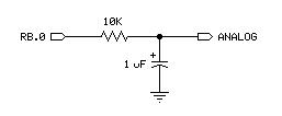
I used the circuit below from the SX help file to produce 0v - 5v via PWM.

Works great.
So I tried to convert that circuit to 12v by replacing RB.0 in the circuit with a SX controlled PNP and feeding it 12v, but no joy. I also tried other Caps.
To be honest I'm not sure a passive circuit like this will handle a CPU fan.
Every project has requirements, so here are mine.
1) I am only making one or two of these testers so cost effectiveness is not that important.
2) Time is important so if I could source the parts for the circuit from my local Radio Crack then I might be done by this weekend.
3) Did I mention time?
So here is my question.
What is the simplest, most reliable SX circuit that can adjust from 5v to 12v and source an amp or so?
I'm really interested to hear the forums suggestions.
Thanks all.
▔▔▔▔▔▔▔▔▔▔▔▔▔▔▔▔▔▔▔▔▔▔▔▔
- - - PLJack - - -
Perfection in design is not achieved when there is nothing left to add.
It is achieved when there is nothing left to take away.
Post Edited (PLJack) : 3/10/2006 5:20:40 AM GMT
I'm still working on controlling a CPU three wire fan with an SX.(protoboard)
I have made a lot of progress with my understanding of how the fan works.
What I am actually doing is building a CPU fan tester that can test eight fans in succession. This test will consist of spinning the fan up at 12v, then dropping it to 5v. Then slowly step the fan back up to 12v. Then read the RPM of the fan.
For those of you that want to know how CPU fans work there is a great article here.
www.maxim-ic.com/appnotes.cfm/appnote_number/1784
The article is mostly an app note for the MAX6625 but still very informative.
Anyway, I have bread boarded the Low side PWM circuit. Works well.
The problem is that the TACH is jittery because the rotation sensor may or may not have power when the fan spins by. This creates problems for PULSIN.
What I need is linear regulation so that the fan IC always has power.
This means being able to adjust voltage to the fan from 12v to 5v via an SX.
I used the circuit below from the SX help file to produce 0v - 5v via PWM.
Works great.
So I tried to convert that circuit to 12v by replacing RB.0 in the circuit with a SX controlled PNP and feeding it 12v, but no joy. I also tried other Caps.
To be honest I'm not sure a passive circuit like this will handle a CPU fan.
Every project has requirements, so here are mine.
1) I am only making one or two of these testers so cost effectiveness is not that important.
2) Time is important so if I could source the parts for the circuit from my local Radio Crack then I might be done by this weekend.
3) Did I mention time?
So here is my question.
What is the simplest, most reliable SX circuit that can adjust from 5v to 12v and source an amp or so?
I'm really interested to hear the forums suggestions.
Thanks all.
▔▔▔▔▔▔▔▔▔▔▔▔▔▔▔▔▔▔▔▔▔▔▔▔
- - - PLJack - - -
Perfection in design is not achieved when there is nothing left to add.
It is achieved when there is nothing left to take away.
Post Edited (PLJack) : 3/10/2006 5:20:40 AM GMT
257 x 106 - 3K
Comments
Sounds like a cool project.
To control +12V from a stamp or SX pin you need to use a NPN transistor and a PNP transistor connected as a darlinton pair.
Basically the +5V pin controls the NPN transistor and the NPN transistor controls the PNP transistor (which is connected to +!2).
For better accuracy I would use and adjustable voltage regulator controlled by a digital pot.
Bean.
▔▔▔▔▔▔▔▔▔▔▔▔▔▔▔▔▔▔▔▔▔▔▔▔
"SX-Video·Module" Now available from Parallax for only $28.95
http://www.parallax.com/detail.asp?product_id=30012
"SX-Video OSD module" Now available from Parallax for only·$49.95
http://www.parallax.com/detail.asp?product_id=30015
Product web site: www.sxvm.com
"Wise men know when they're right. The wisest also·know when they're wrong."
·
Should be when It's finished.
So, I spent some time on Google.
I did not see a darlington pair (Npn/Pnp) that made sense to me.
The ones I saw have a POT connected to the circuit.
Like this one:
www.eleinmec.com/article.asp?21
I guess what I need is an adjustable linear voltage via PWM.
And adjust the voltage by pulsing the pin?
Will this produce a non-pulsing voltage?
Your description sounds like what I want, but I can't see it in my head.
▔▔▔▔▔▔▔▔▔▔▔▔▔▔▔▔▔▔▔▔▔▔▔▔
- - - PLJack - - -
Perfection in design is not achieved when there is nothing left to add.
It is achieved when there is nothing left to take away.
You already have what Bean has sugested - replace the pot in your attached diagram (http://www.eleinmec.com/article.asp?21) with the output pin of the SX, then send pulses from the SX pin.· You will create different voltages by sending different duty cycles.· The pulsed output is smoothed into a smooth(er) voltage by the impedance of the motor coils.· (20 KHz is often used as a frequency for driving small DC motors.)
****EDIT - Whoops, just re-read your first post - If you are·not driving the motor coils directly (driving some sort of IC), you will need·put something on·the output of the darlington to help smooth the pulsed voltage.· You could put a cap as you have shown, may need to calculate size needed dependant on the current draw of the IC and your pulse frequency.
Might want to go with Bean's second idea, the variable voltage regulator controlled by a digital pot.
Nate
Post Edited (Nate) : 3/11/2006 3:30:10 AM GMT
That thought occurred to me after I posted.
Thanks for confirming that for me.
I'm not sure how important that is. It is a brushless motor so it must have an IC to imitate brush contacts.
The motor runs fine under straight PWM, but the third wire (tach) does not perform well under on/off voltage.
That sounds like the best solution.
Still, I'm going to try this circuit and see what the results are.
Thanks for posting guys.
▔▔▔▔▔▔▔▔▔▔▔▔▔▔▔▔▔▔▔▔▔▔▔▔
- - - PLJack - - -
Perfection in design is not achieved when there is nothing left to add.
It is achieved when there is nothing left to take away.
▔▔▔▔▔▔▔▔▔▔▔▔▔▔▔▔▔▔▔▔▔▔▔▔
·1+1=10
Allen, Thank You!
I was glad to see 15V feeding the Op Amp because I was planing to power the test unit with 16V.
I bread boarded your circuit with 16V and it works great.
PULSIN is reading between 4ms and 3ms. My scope reads 3.6ms, so I would say that is pretty close.
One issue though.
If I bring the source pin low (the PWM pin) I read 4.18 volts at V Out.
With a PWM of "PWM Fan_0, 255, 50" I read 10.18V at V Out.
I really need to place 12V at the fan input.
I may have to test 5V fans as well so this is a bit of an issue.
I just re-checked my bread board and resistor/cap values and it conforms to the circuit
Any ideas on producing 0V and 12V?
Thanks all.
▔▔▔▔▔▔▔▔▔▔▔▔▔▔▔▔▔▔▔▔▔▔▔▔
- - - PLJack - - -
Perfection in design is not achieved when there is nothing left to add.
It is achieved when there is nothing left to take away.
Post Edited (PLJack) : 3/13/2006 1:53:49 AM GMT
· If the output isn't getting to 12V, then the op-amp input, the conditioned 'PWM' may not be getting up to 5V.· Try changing the feedback resistor, the 47K, to a POT (100K).· This will make the op-amp's gain Adjustable.· If you're testing for output: place a 10-22uF (make sure its WVDC is >·Vout) on·the output along with a 1/2W 1K resistor (these two would be from output to Ground -- not in series with the output.)
· Also, make sure that your power supply (the 15V) isn't dropping out, or drooping, under load.
Edit Addendum -->
· One other thing --·the 1uF cap (the 'PWM' smoothing network) may need a "bleeder" resistor.· The op-amp has a very-high input impedance and therefore doesn't·load that cap much: it'll stay up after the 'PWM' goes off.· So, try a 10K at the op-amp "+" to Ground (you can experiment with lower values.)
· [noparse][[/noparse]If you Ground the "+" pin, then the output should be 0V.· Do this with the PWM pin disconnected.]
Post Edited (PJ Allen) : 3/17/2006 1:10:45 PM GMT
To get up to 12 volts at the output, both of the transistors and also the op-amp output would be operating near saturation, so the drive currents will increase, and the 4.7k resistor will drop some voltage. If you power it from 16 volts, all the better, because it needs the overhead.
10k to ground at the output will help the LM358 output pull all the way to ground to shunt any leakage current from the transistors. Put your oscilloscope probe on the output of the op amp when the PWM input is set to LOW. There should not be any oscillation, the output should be solid zero, and the Vout should also be solid zero.
▔▔▔▔▔▔▔▔▔▔▔▔▔▔▔▔▔▔▔▔▔▔▔▔
Tracy Allen
www.emesystems.com
I'm off to the lab. I'll post the results.
▔▔▔▔▔▔▔▔▔▔▔▔▔▔▔▔▔▔▔▔▔▔▔▔
- - - PLJack - - -
Perfection in design is not achieved when there is nothing left to add.
It is achieved when there is nothing left to take away.
Allen, Your suggestions produced 12v with PWM high. Thanks.
Unfortunately I still have the 4v with the PWM pin low.
So as I was pondering what I had done wrong with my circuit I started to think that a voltage regulator and a digital pot are only a handful of dollars.
I am all for working out problems for the experience, but this is not one of those times.
So I have a few of these coming tomorrow from Mouser:
Digital Potentiometer
www.mouser.com/index.cfm?&handler=data.listcategory&D=698-CAT5112P-00&terms=698-CAT5112P-00&Ntt=*698CAT5112P00*&N=0&crc=true
Voltage Reg 3Term adjustable
www.mouser.com/index.cfm?handler=displayproduct&lstdispproductid=209806&e_categoryid=260&e_pcodeid=51238
What do you think? Should work fine, right?
Again, my goal is to produce 0V and step up to 12V.
As a bonus I get to drop PWM for motor control. Should keep the code simple.
▔▔▔▔▔▔▔▔▔▔▔▔▔▔▔▔▔▔▔▔▔▔▔▔
- - - PLJack - - -
Perfection in design is not achieved when there is nothing left to add.
It is achieved when there is nothing left to take away.
With the original circuit, did you measure the voltage at the output of the op amp (pin 1 or pin 3) when the PWM was at zero and output from the transistors was strangely at 4 volts? If the op amp output is zero, as it should be, that would indicate either that you have very leaky transistors, or that there is a sneak path back into Vout. What happens if you replace the fans with a 12 volt 100 ma light bulb to ground?
▔▔▔▔▔▔▔▔▔▔▔▔▔▔▔▔▔▔▔▔▔▔▔▔
Tracy Allen
www.emesystems.com