

Accessory project: Pimp my Professional Development Board (PDB)
 CarlC
Posts: 29
CarlC
Posts: 29
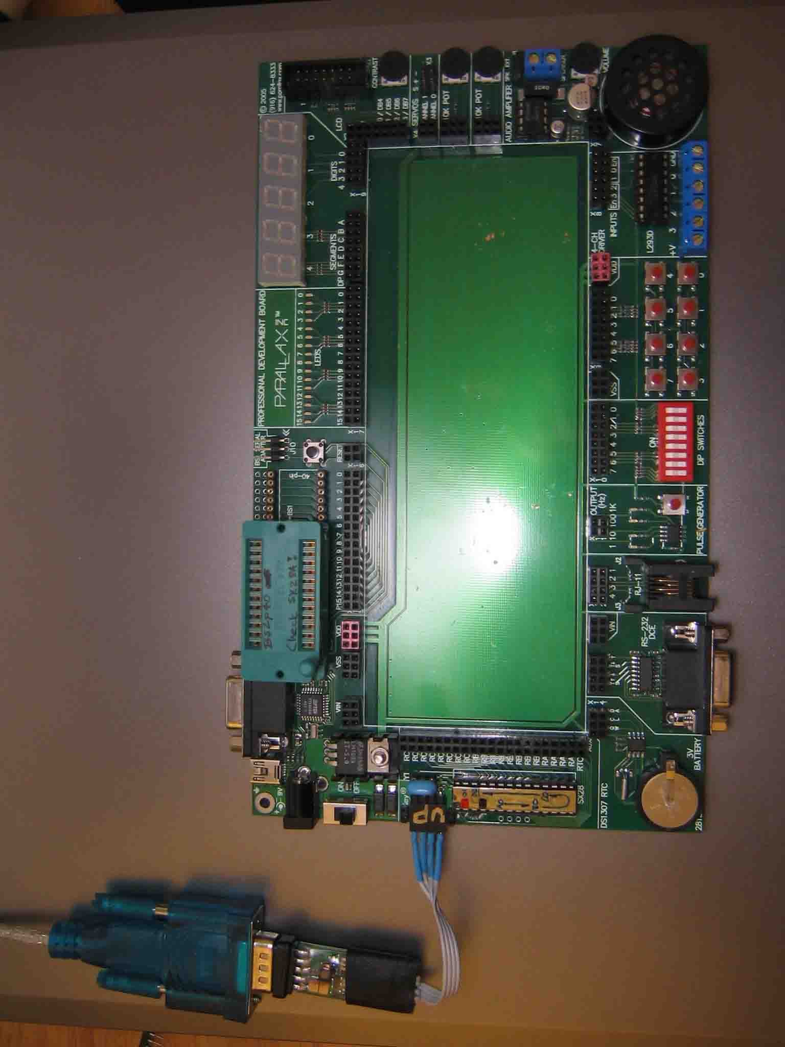
I found myself reluctant to take projects off of my PDB especially after a painstaking wiring debugging session. Unfortunately working on a new project means that I have to work out biased switch inputs or LEDs with discrete resistors on a breadboard on the side. I also have to work out STAMP or SX programming connections.
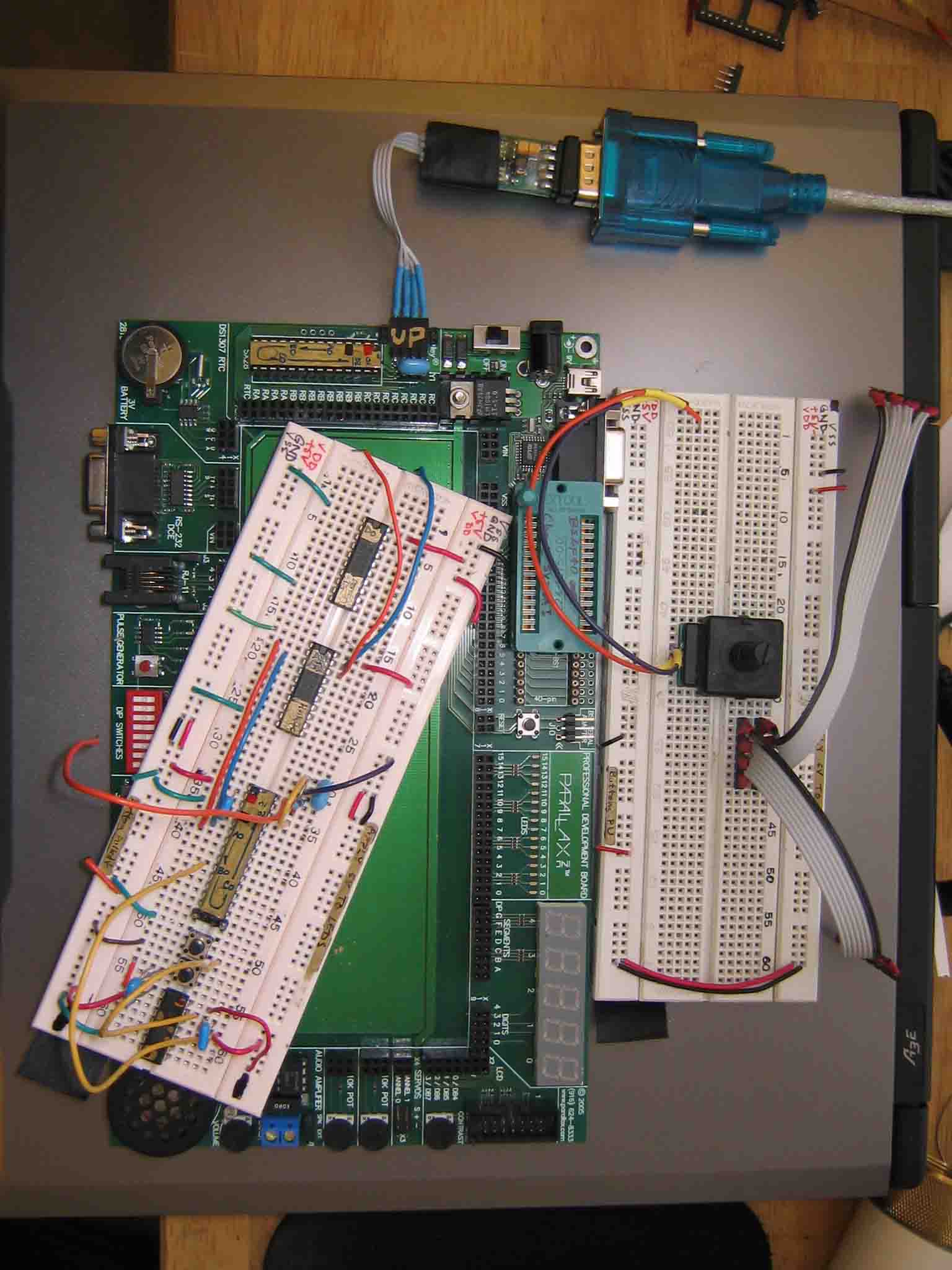
After tearing down my last project to demonstrate some STAMP ideas for a friend, I had an idea: Dismount the breadboard to make it easily removable so I can modularly swap in a breadboard module taken from a regular breadboard which doesn't come with all the nice features of the Parallax PDB.
It worked out nicely. I found that the board is mounted with double sided foam tape. I was able to pry the board off after leaving it in my oven which was warmed up to a toasty 60C. I turned the elements on for a few minutes and turned them off to I wouldn't accidentally overheat the entire thing and damage something. I removed the battery for the RTC too.
With some gentle prying with a flathead screwdriver and some rubbing alcohol to dissolve the adhesive, I was able to remove the breadboard section. Be careful, don't use a screwdriver with sharp corners. You might damage the top layer of copper (shielding?) under the breadboard. I note some piercepoints so I think there are a few connections to the copper layer directly under the breadboard.
I pasted a layer of thin cardboard under the breadboard to replace the foam tape that I removed to keep the same spacing and to separate the breadboard from the copper layer.
The now modular breadboard can be swapped with breadboards from other breadboard protoboards as they often made to the same size standards.
My next small project is to make ribbon cable pin headers to modularly connect to connect to the soldered sockets like button inputs or the I/O pins for the processer.
Post Edited (CarlC) : 2/8/2006 11:23:48 PM GMT
1536 x 2048 - 113K
1536 x 2048 - 154K
Comments
▔▔▔▔▔▔▔▔▔▔▔▔▔▔▔▔▔▔▔▔▔▔▔▔
Chris Savage
Parallax Tech Support
csavage@parallax.com
At the bottom right corner of my boards, I put on a cloth tape tag to make it easier to remove the breadboards.
I'm making some socket headers so wires to external devices (eg. RB ports) can be modularly connected.