

Digital Sine wave...
 Beau Schwabe
Posts: 6,576
Beau Schwabe
Posts: 6,576
Anyone have some clever code to generate a pseudo sine wave?
Eventually this will be implemented in a frequency sweep application for doing Bode plots.
(Bean, your audio generation project gave me an idea for this.)
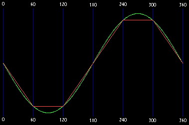
Right now I have a scheme that requires two I/O pins that are "flipped" at the same time,
with one lagging the other by 60 Deg.
In the attached image, Green is the ideal sine, while the Red is the actual sine wave.
▔▔▔▔▔▔▔▔▔▔▔▔▔▔▔▔▔▔▔▔▔▔▔▔
Beau Schwabe
IC Layout Engineer
Parallax, Inc.
Post Edited (Beau Schwabe (Parallax)) : 2/5/2006 6:49:06 PM GMT
Eventually this will be implemented in a frequency sweep application for doing Bode plots.
(Bean, your audio generation project gave me an idea for this.)
Right now I have a scheme that requires two I/O pins that are "flipped" at the same time,
with one lagging the other by 60 Deg.
A >----/\/\----o--||--> +V
               |
               0------> Out
               |
B >----/\/\----o--||--> GND


A  B   SinePhase
0  1       0
0  0      60
0  0     120
1  0     180
1  1     240
1  1     300
In the attached image, Green is the ideal sine, while the Red is the actual sine wave.
▔▔▔▔▔▔▔▔▔▔▔▔▔▔▔▔▔▔▔▔▔▔▔▔
Beau Schwabe
IC Layout Engineer
Parallax, Inc.
Post Edited (Beau Schwabe (Parallax)) : 2/5/2006 6:49:06 PM GMT
379 x 252 - 17K
Comments
There are Don Lancaster's "magic sine" algorithms, a special form of PWM that minimizes harmonics.
www.tinaja.com/magsn01.asp
PIC code is there, but it is a sure bet the SX could do it more efficiently. What frequency range are you looking at?
There are also the MF10 series digital filter chips, that can generate sine waves (with feedback from output to input) dependent on the input clock frequency. Audio range and below. There are also the DDS chips, like the AD9850, that cover a huge frequency range from sub Hertz to 60 mhz.
▔▔▔▔▔▔▔▔▔▔▔▔▔▔▔▔▔▔▔▔▔▔▔▔
Tracy Allen
www.emesystems.com
I have seen this, and actually have implemented it, but it eats up allot of CPU cycles.
"What frequency range are you looking at?"
To start off, I would be happy with DC to a few MHz (5? 10?)... Once you get to 10MHz
or so, a square wave starts looking like a sine, and I could just go up from there.
I'm still not sure what step increment I want though. I have an idea for a wide range
VCO that could drive the OSC pin of an SX for the lower frequencies.
I will look into the AD9850 as an option.
▔▔▔▔▔▔▔▔▔▔▔▔▔▔▔▔▔▔▔▔▔▔▔▔
Beau Schwabe
IC Layout Engineer
Parallax, Inc.
Is there some reason you can't use a whole 8-bit port for this, to push out the sine wave in parallel?
There have been several threads on the Stamps list about how to calculate the control word (24 bits) for the AD9850 DDS.
▔▔▔▔▔▔▔▔▔▔▔▔▔▔▔▔▔▔▔▔▔▔▔▔
Tracy Allen
www.emesystems.com
I don't have a problem with using the entire 8-bit port to bit-bang a sine wave via a R2R dac, but I don't gain any more
CPU time doing it that way vs with the 2-pin method I mentioned above. I think even a triangle wave would work using the
two pin method with a 90 Deg phase lag.
▔▔▔▔▔▔▔▔▔▔▔▔▔▔▔▔▔▔▔▔▔▔▔▔
Beau Schwabe
IC Layout Engineer
Parallax, Inc.
What kind of distortion can you tolerate?
I figure to generate a so-so sinewave with a single RC pin PWM can be done with 15 instructions per sine value, and there would need to be an absolute minimum of 8 segments to one sine cycle.....the more the purer the result. So that sounds like 120 instructions at 20 nanoseconds each, for a one cycle total of 2.4 usec. That's only about 400 Khz; quite a ways from your target.
Cheers,
Peter (pjv)
I would be willing to see what you have in the way of code for this.
▔▔▔▔▔▔▔▔▔▔▔▔▔▔▔▔▔▔▔▔▔▔▔▔
Beau Schwabe
IC Layout Engineer
Parallax, Inc.
In the Parallax contest I entered a "Small Hardware and Development Board" project which incidentally had dual sinewaves with separately selectable frequencies generated by the "single pin PWM" method. While the sine waves were not the primary purpose of the entry, they demonstrate a reasonable way of getting good results, albeit quite a bit slower than what you are looking for.
If you poke at that entry (sorry, I don't know how to make the link for you), you can see the photograph of two sine traces on the 'scope.
Take a peek at the code to see how the ISR updates each PWM accumulator, and how the scheduler selects the sine value. The scheduler also drives the raise/lower buttons to control each frequency. It can very easily be modified to have the sceduler sweep through a range of frequencies. And of course, the amplitude is frequency independent.
Again, that project was not as fast as you would like, but by carving off the "niceties", I think it's possible to get things down to the speeds I indicated; about 400 KHz.· If you would like me to spend some time poking at that, I'd be happy to oblige.
;==============================================================================
;TITLE:··Sines.src
;
;PURPOSE:·Demonstrate a the effectiveness of an SX development board by
;··implementing a simple non-preemptive multi tasking scheduler
;··operating a dual pulse density modulation sine wave generator.
;
;AUTHOR:·Peter Van der Zee, Datek Industries Inc.
;
;REVISIONS:·Feb 27, 2005 Original.
;
;CONNECTIONS:·Port:·b.0·button to lower frequency 1
;···b.1·button to raise frequency 1
;···b.2·button to lower frequency 2
;···b.3·button to raise frequency 2
;
;··Port:·c.0·output as frequency 1· PWM output to RC filter 1.
;···c.2·output as frequency 2· PWM output to RC filter 2.
;
;DETAILS:·Each of two independent simple sine wave generators operate by
;··pulse density modulating an output bit in a deterministic
;··Interrupt Service Routine. A tick based task scheduler controls
;··frequency selection control and sine value calculation for each
;··of the generators.
;
;··The scheduler demonstrates multiple independent tasks operating
;··without much concern of each other with·the exception of being
;··non-preemptive in nature. In other words, a task that requires
;··more rapid response will not interrupt a slower task already
;··running or scheduled to run. For greater determinism it is
;··important that no task "hogs" a lot of processor time in any
;··run instance, and it is absolutely crucial that no task uses
;··long delay loops. The purpose of the scheduler is to remove the
;··in-line·requirement for delays by letting the scheduler provide
;··those instead.
;
;··In the generators, the sine value resolution is purposely left
;··coarse so on an oscilloscope the user can see the fixed effect
;··of frequency adjustment through raise/lower buttons.
;··Finer resolution can be conveniently made by expanding access
;··and granularity of the sine lookup table, albeit at the expense
;··of maximum frequency.
;
;··It should be obvious that replacing the sine lookup table with
;··a ramp value table, a sawtooth table or·any random function table
;··that other functions can be equally easily generated.
;
;··The scheduler time ticks are set to convenient numbers, in this
;··case permitting task threads to be executed at even decades of
;··time from the base tick of 1 usec for the ISR, to 10 and 100 usec,
;··1, 10 and 100 msec, and 1 sec. The scheduler can be easily altered
;··for more or less resolution, the major stipulation being that each
;··slower tick is an integer multiple of the previous tick.
;··More complicated arrangements can of course be made. Where mutiple
;··tick (non-decade) delays are required in a thread, then the thread
;··itself is tasked with the requirement to do so.
;==============================================================================
ResetEntry
  ;Initialize the ports
SetLevels mov m,#$0d           ;Set 0 for CMOS levels
          mov !ra,#%0000       ;
          mov !rb,#%0000_0000  ;
          mov !rc,#%0000_0000  ;
SetPullups mov m,#$0e          ;Set 0 for pullups
          mov !ra,#%0000       ;port a not used
          mov !rb,#%0000_0000  ;input buttons
          mov !rc,#%1111_1111  ;
SetTris   mov m,#$0f           ;Set 0 for output
          clr ra
          mov !ra,#%1111       ;port a not used
          clr rb               ;
          mov !rb,#%0000_1111  ;X,X,X,X _ F2up,F2dn,F1up,F1dn
          clr rc               ;
          mov !rc,#%0000_0000  ;X,X,X,X _ X,DAC2,X,DAC1
;Clear memory Clearmem mov fsr,#$10 ;point to first memory bank Clearone setb fsr.4 ;stay in proper half clr ind ;clear this location incsz fsr ;point to next location jmp Clearone ;not at end so clear one more;Initialize the scheduler timers mov w,#10 ;timer decade value mov Timer10uS,w ;10 microseconds mov Timer100uS,w ;100 microseconds mov Timer1mS,w ;1 millisecond mov Timer10mS,w ;10 milliseconds mov Timer100mS,w ;100 milliseconds mov Timer1S,w ;1 second;Initialize the variables clr rtcc ; mov !option,#%1000_1000 ;internal rtcc clr Flags ; mov Dac1Value,#128 ;set initial value of dac1 half way mov Dac2Value,#128 ;set initial value of dac2 half way ;---------------MAIN PROGRAM---------------------------------------------------Main sb Intflag ;test for interrupt occurred jmp Main ;wait for interrupt bank Ram1 ; Usec1 clrb Intflag ;clear that fact decsz Timer10uS ;scheduler 1 usec base tick jmp Main ;wait for occurrence of next interrupt Usec10 mov Timer10uS,#10 ;reload 10usec timer ;put 10 uSec routines here call Sine1 ;determine freq 1 step call Sine2 ;determine freq 2 step decsz Timer100uS ;scheduler 10 usec tick jmp Main ;wait for occurrence of next interrupt Usec100 mov Timer100uS,#10 ;reload 10usec timer ;put 100 uSec routines here decsz Timer1mS ;scheduler 100 usec tick jmp Main ;wait for occurrence of next interrupt Msec1 mov Timer1mS,#10 ;reload 100usec timer ;put 1 mSec routines here decsz Timer10mS ;scheduler 1 msec tick jmp Main ;wait for occurrence of next interrupt Msec10 mov Timer10mS,#10 ;reload 1msec timer ;put 10 mSec routines here decsz Timer100mS ;scheduler 1 usec base tick jmp Main ;wait for occurrence of next interrupt Msec100 mov Timer100mS,#10 ;reload 10usec timer ;put 100 mSec routines here sb rb.0 ;test button for lower frequency 1 call Lower1 ;decrease frequency 1 sb rb.1 ;test button for higher frequency 1 call Higher1 ;increase frequency 1 sb rb.2 ;test button for lower frequency 2 call Lower2 ;decrease frequency 2 sb rb.3 ;test button for higher frequency 2 call Higher2 ;increase frequency 2 decsz Timer1S ;scheduler 1 usec base tick jmp Main ;wait for occurrence of next interrupt Sec1 mov Timer1S,#10 ;reload 10usec timer ;put 1 Sec routines here jmp Main ;wait for occurrence of next interruptLower1 ;reduce frequency of generator 1 but not below zero incsz Period1Load ;increase the period of frequency 1 skip ; dec Period1Load ;underflow not permitted retp ;Higher1 ;increase frequency of generator 1 but not above $ff decsz Period1Load ;decrease the period of frequency 1 skip ; inc Period1Load ;overflow not permitted retp ;Lower2 ;reduce frequency of generator 2 but not below zero incsz Period2Load ;increase the period of frequency 2 skip ; dec Period2Load ;underflow not permitted retp ;Higher2 ;increase frequency of generator 2 but not above $ff decsz Period2Load ;decrease the period of frequency 2 skip ; inc Period2Load ;overflow not permitted retp ;Sine1 ;calculate lookup time for generator 1, and if so, get sine value decsz Period1 ;step frequency 1 period duration retp ;not time for next sine lookup; return to scheduler mov Period1,Period1Load ;reload period 1 timer inc F1index ;step to next sine value in lookup table mov w,F1index ; call SineLookup ;get sine value for this index mov Dac1Value,w ;setup new dac 1 value for the ISR retp ;done freq1; return to schedulerSine2 ;calculate lookup time for generator 2, and if so, get sine value decsz Period2 ;step frequency 2 period duration retp ;not time for next sine lookup; return to scheduler mov Period2,Period2Load ;reload period 2 timer inc F2index ;step to next sine value in lookup table mov w,F2index ; call SineLookup ;get sine value for this index mov Dac2Value,w ;setup new dac 2 value for the ISR retp ;done freq2; return to schedulerSineLookup ;lookup the sine value of index in w and w,#%0000_1111 ;only use 16 steps in lookup table add pc,w ;calculate offset into lookup table Sin0 retw 128 ;$80 Sin1 retw 177 ;$b1 Sin2 retw 218 ;$da Sin3 retw 245 ;$f5 Sin4 retw 255 ;$ff Sin5 retw 245 ;$f5 Sin6 retw 218 ;$da Sin7 retw 177 ;$b1 Sin8 retw 128 ;$80 Sin9 retw 79 ;$4f SinA retw 38 ;$26 SinB retw 11 ;$b SinC retw 1 ;$1 SinD retw 11 ;$b SinE retw 38 ;$26 SinF retw 79 ;$4fCheers,
Peter (pjv)
I'll have a look and see what I can do.
▔▔▔▔▔▔▔▔▔▔▔▔▔▔▔▔▔▔▔▔▔▔▔▔
Beau Schwabe
IC Layout Engineer
Parallax, Inc.
The biggest problem you face is the lack of IO pins and your desire to avoid PWM.
The first thing that jumps to mind is to calculate the exact sinewave value (table or the link above) and then just use the top 2 or three bits of it, but accumulate the error from the other bits that are not used and total that into the next value. The result will be that at lower frequencies, you will have some PWM "effect" where one or both of the pins switch on and off rapidly to compensate for the error and at higher frequencies, there will be no time for that and you will get more like a squarewave.
Not sure if that makes sense...
▔▔▔▔▔▔▔▔▔▔▔▔▔▔▔▔▔▔▔▔▔▔▔▔
---
James Newton, Host of SXList.com
james at sxlist,com 1-619-652-0593 fax:1-208-279-8767
SX FAQ / Code / Tutorials / Documentation:
http://www.sxlist.com Pick faster!