

Help me..
 xaer8
Posts: 15
xaer8
Posts: 15
Hi there.. (sorry about my lacks in english language, though i try my best·)
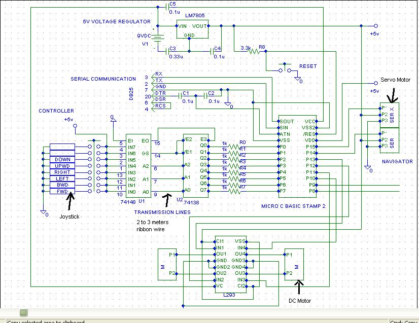
I'm a new basic stampII user, bought it just a month ago. Maybe the i'm the first in my college to use it.·So i'm a bit confused and not sure about the circuit i constructed although after i've referred to lots of manuals and webpages. Actually it is for my final year project on mini swimming robot. I interfaced a direct connection switches which appeared as a joystick to the robot. Then i used an encoder and decoder to reduce my communication line to the basic stamp·as·my robot is using wired communication to control, not wireless. Furthermore,·i used L293 to make·my tamiya motor unit to be able to run on cw and ccw, plus two·standard servos. This robot does not have any sensor with it, because i'm the one who will control it so any sensor is not necessary i think. But·i felt something isn't right about this circuit. So i·would hugely appreciate all of·your kindness to reply me comments or suggestions·on this circuit.·I·register and join·this forum today espcially for this purpose. Please..
I'm a new basic stampII user, bought it just a month ago. Maybe the i'm the first in my college to use it.·So i'm a bit confused and not sure about the circuit i constructed although after i've referred to lots of manuals and webpages. Actually it is for my final year project on mini swimming robot. I interfaced a direct connection switches which appeared as a joystick to the robot. Then i used an encoder and decoder to reduce my communication line to the basic stamp·as·my robot is using wired communication to control, not wireless. Furthermore,·i used L293 to make·my tamiya motor unit to be able to run on cw and ccw, plus two·standard servos. This robot does not have any sensor with it, because i'm the one who will control it so any sensor is not necessary i think. But·i felt something isn't right about this circuit. So i·would hugely appreciate all of·your kindness to reply me comments or suggestions·on this circuit.·I·register and join·this forum today espcially for this purpose. Please..
826 x 637 - 122K
Comments
· I guess you're going to walk alongside it with it swimming in a pool.· I see that you're going to use a cable between U1 & U2.· Pour quoi?··So, why not just extend the joystick cable instead?· (I suppose you're trying to minimize the number of wires in the cable.)
· It's possible that, either way, you may couple noise (depending upon the environment) into the circuit.
· If you converted to digital coding for the joystick directions, then you could use RS-232 between your joystick-controller unit and the robot (and that would be only three wires·in a nice shielded cable.)· This way, you could easily implement a wireless solution (R/C).
Post Edited (PJ Allen) : 2/5/2006 4:26:25 PM GMT
Thanks for the nice and brilliant suggestion. Of course i intended to minimize the number of wires in the cable, but you came up with better solution. Thanks..really. If i implement a wireless solution (R/C), what types of R/C product would you suggest? Can i use the one that already exist in the R/C car toy and modify it to use as my wireless communication? I wish to focus more on finishing this project with the least time consume and the least money could cost. So if possible i would use R/C rather than cable. But if that is not possible, then maybe i will stick with using cable. But i'll consider using your good idea. Any other suggestion or correction on this circuit? Maybe the capacitors and resistors placement and value? I wish to make this project simple but a good one. There aren't many swimming or underwater robot project for me to refer...
▔▔▔▔▔▔▔▔▔▔▔▔▔▔▔▔▔▔▔▔▔▔▔▔
Let's try our best together!
Since RF doesn't travel well underwater, you will need a surface mounted antenna, so wireless may not be the best route to take.
Regards,
Bruce Bates
· Is it a surface-skimmer (like a boat) or a submarine?· Since you said swimmer, I assumed that it stays on the surface.· I guess there's "upwd" and "down", so...
· Anyway, if your hand-held (joystick) unit had a BS1, you could convert the directions to a digital code and send that serially/RS-232 with a lightweight cable to the swimmer.· I would send an attention byte followed by a direction byte:
· 01011010 -- attention ($5A = "Z")
· 00000000 -- none/no change
· 00000001 -- down
· 00000010 -- up
··00000100 -- right
· 00001000 -- left
· 00010000 -- bwd
· 00100000 -- fwd
· So, the swimmer would wait to receive a "Z" and know that the next byte would be a direction byte.
It's a swimming robot, but could also dive underwater without using any balast or air valve that could enable it to submerge like submarine. Up and down means it swim downward and upward..more like a turtle, not fish. And i prefer not to use another basic stamp at my control unit (joystick). That's why i used direct connections (from 5V, active low) which more like switches(a.k.a. joystick too) to control my robot. Is it possible?
▔▔▔▔▔▔▔▔▔▔▔▔▔▔▔▔▔▔▔▔▔▔▔▔
Let's try our best together!
Post Edited (PJ Allen) : 2/5/2006 8:40:50 PM GMT
▔▔▔▔▔▔▔▔▔▔▔▔▔▔▔▔▔▔▔▔▔▔▔▔
Let's try our best together!
▔▔▔▔▔▔▔▔▔▔▔▔▔▔▔▔▔▔▔▔▔▔▔▔
Jon Williams
Applications Engineer, Parallax
One more thing, can i apply 9V to VC and 5V to VSS of L293. I'm afraid the output of L293 could not give enough power to both tamiya motor to thrust the robot to swim on and dive underwater. Any suggestion?
▔▔▔▔▔▔▔▔▔▔▔▔▔▔▔▔▔▔▔▔▔▔▔▔
Let's try our best together!
I believe you must use the Vc pin on the L293 (you can use 9v) as the 5v input is for the chip's logic. It's been a while since I've used one, so you might want to check the datasheet in case I'm mistaken.
▔▔▔▔▔▔▔▔▔▔▔▔▔▔▔▔▔▔▔▔▔▔▔▔
Jon Williams
Applications Engineer, Parallax
▔▔▔▔▔▔▔▔▔▔▔▔▔▔▔▔▔▔▔▔▔▔▔▔
Let's try our best together!
▔▔▔▔▔▔▔▔▔▔▔▔▔▔▔▔▔▔▔▔▔▔▔▔
Jon Williams
Applications Engineer, Parallax
Thanks for all the help. After 12 postings full of questions and answers, i come up with the latest circuit (after few adjustments). I've already change LM7805 to LM2940, using 22uF and 0.47uF. I've connect regulated 5V directly to VDD (pin21) of BS2 and left VCC (pin24) unconnected. I also have 2 extra input pins at the jostick and 2 extra pins at my BS2. Now what? I still feel empty and imperfect about whole this circuit. Any suggestion or correction would be most welcome...
▔▔▔▔▔▔▔▔▔▔▔▔▔▔▔▔▔▔▔▔▔▔▔▔
Let's try our best together!
▔▔▔▔▔▔▔▔▔▔▔▔▔▔▔▔▔▔▔▔▔▔▔▔
Jon Williams
Applications Engineer, Parallax
I find during debugging that having an LED being blinked by my 'main loop' code to be a very re-assuring thing. And even during running, having that LED winking at me tells me my program continues to work.
And if you have a logic analyzer of any description, your code can toggle pulses on that LED pin that the logic analyzer can read, to tell you what part of your program you are running.
By the way, the other two extra input pin at the hand-held(joystick), how can i make one of them as a 'start' button and one as 'stop' button? What i mean here is as long as i didn't push the 'start' button, any 'up', 'down'.. etc input would be neglected by BS2 and 'Stop' button would stop any activity (neglect any input also) but only accept 'start' button to be pushed again. Is that possible to do in my program? Have any better suggestion?
▔▔▔▔▔▔▔▔▔▔▔▔▔▔▔▔▔▔▔▔▔▔▔▔
Let's try our best together!
▔▔▔▔▔▔▔▔▔▔▔▔▔▔▔▔▔▔▔▔▔▔▔▔
Let's try our best together!
status var word
status = 0 'OFF
main:
if status = 0 then is_off
if status = 1 then check_for_off
rest of code here
goto main
is_off:
(Check to see if Start button is pressed)
--if so set status = 1
goto main
check_for_off:
(Check to see if Stop button is pressed)
--If so set status = 0
--goto main
--else
--return
Just my idea
The result will be something like welding shut the switch, shorting out +5, removing power from the 74138, and probably resetting your project.
However, if you simply add a 10 Kohm resistor between the 74138 input pin and +5 volts, then when you push the button on that switch the 74138 pin side of the resistor will go to zero volts. The +5 volts is now 'dropped' across that 10 Kohm resistor, which harms nothing, and makes the circuit work the way you want it to. It's called a "pull-up resistor", and is essential for what you are doing.