

USB cable to control BS2
 Jason Short
Posts: 21
Jason Short
Posts: 21
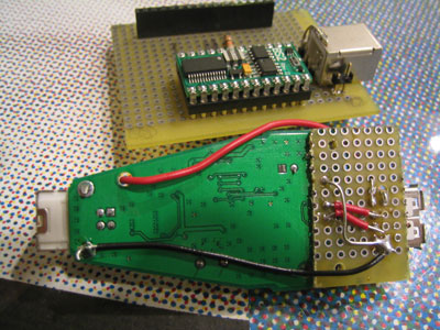
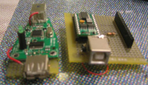
I'm working on some controllers that I'm driving with BS2s and I use a Keyspan USB-serial adapter to connect them. I thought it might be a nice trick to use a USB cable from the keyspan adapter to the stamp. The cable has 4 lines, Ground, +5, Data Out,Data In. I removed the DB9 connector from the adapter and soldered on a Type A USB connecter and ran the lines to it.
My power situation on the stamp is good. It powers on and works well. The issue is the RS232 connection. When I look at it with my little scope all I see is noise on the pins when they transmit. On my development board I see nice square waves.
My question is where is this noise coming from and how can I steal power and ground from this USB adapter? I figure I have some kind of ground issue but I'm totally ignorant on how to track it down.
http://www.keyspan.com/products/usb/USA19HS/
Thanks,
Jason
400 x 300 - 50K
300 x 173 - 21K
Comments
Why would you want to hack a perfectly good USB to serial adapter, to make a BS2 board which 'looks like' it has a USB connection, only it's some weird RS-232 over USB hardware hybrid.
The RS232 hardware on the BS2 'Port 16' programming port uses the incoming RX signal to power its outbound TX signal, so that has to be good.
And you can't 'reset' the BS2 over the serial link if you don't connect the DTR signal -- so a minimal BS2 cable MUST have TX, RX, GND, and DTR. And for programming to 'see' it, the RTS and CTS (pin 7 and 8) signals need to be looped back.
So, to use it, you need TX,RX, and GND. To program it, you need those plus DTR, RTS, and CTS.
Were I you, and in a hacking mood, I'd probably use an RJ45 connector and cable over the USB. You get more conductors (8), you get more distance, cable is cheaper, and you won't confuse people who WILL plug your BS2 module directly into a "REAL" USB port, with disasterous results.
Oh, and powering the BS2 from the cable -- USB doesn't have enough pins for that, but you COULD use one conductor of the RJ45 cable for that purpose.
For that matter, you could have 'lifted' one of the 'unused' DB-9 pins off the Keyspan (like pin 1, maybe), routed +5 to it from the Keyspan, and used THAT as your power source for the BS2.
·
I never intended to program the stamp from this. It's for a set of 4 embedded prototypes that need to be run off of a single keyspan adapter and swapped out many times. The USB is a nice cable for that and I happened to have the USB board mount connectors already. If I used an Ethernet I would run into a similar problem with pulling the power from the USB hub itself which is at the heart of my question. Of course I could add a real power supply and run separate power and ground to the stamp and I'm sure that would work, but I thought the USB already has 5v and ground so why not tap in?
I'm just curious why the RS-232 isn't working, because the power is working fine. And yes I was in a hacking mood!
Thanks
Please keep in mind that an un-enumerated USB connection can NEVER draw more than 100 mA under any conditions. To do so may cause the entire USB port to shut down.
If you don't fully understand what I'm speaking about here, you probably shouldn't be trying to use parasitic power from a USB port. There is even more to it than what I've just said.
Regards,
Bruce Bates
Jason
What you understand is NOT correct, per the USB 2.0 Specifications. Please download the complete USB Specifications from the link below and read through it, the same as I did, before you continue, since motherboards don't come cheap these days!
http://www.usb.org/developers/docs/
Regards,
Bruce Bates
http://www.parallax.com/detail.asp?product_id=604-00043
jason
▔▔▔▔▔▔▔▔▔▔▔▔▔▔▔▔▔▔▔▔▔▔▔▔
Jon Williams
Applications Engineer, Parallax
Jason