

RFEFX Board

Man,
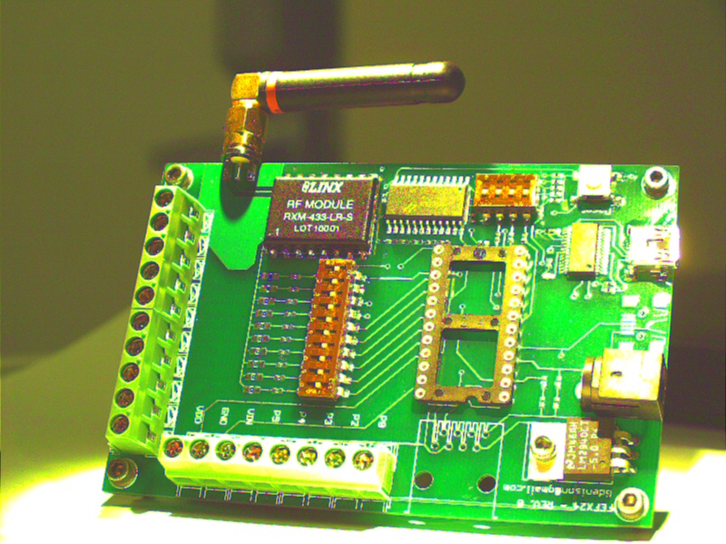
I can't say how long I have been working on this project. Well its finally done. I present to you my RFEFX board. i never really was a BS1 person, no offense parallax, I like my BS2's. the board has many features that some of you may like or may not like.... its your opinion.
Let see... let me start by saying, I dislike Bread Boards, so this was designed not to utilize them.
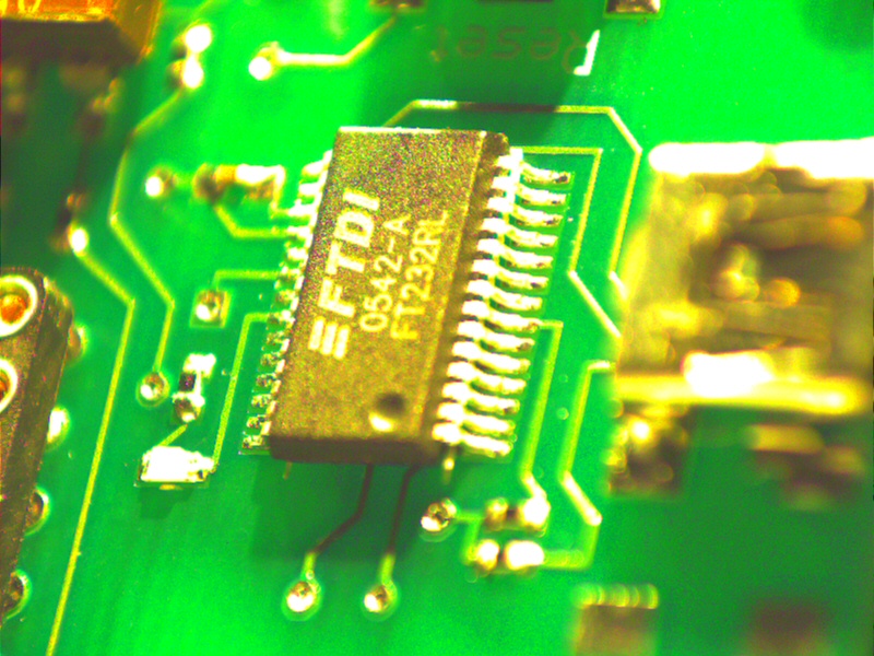
I was tired of the Serial connection so using a FTDI FT232RL chip (from Parallax) I eliminated the serial. I also wanted direct terminal connectivity to the BS2 (I use SX version) so the terminal blocks were a must. i also wanted the capability of LEDs, so I put them in but there in line with a 10 position dipswitch (the LEDs are not installed in the picture). I use 0805 Surface mount LEDs for my board.
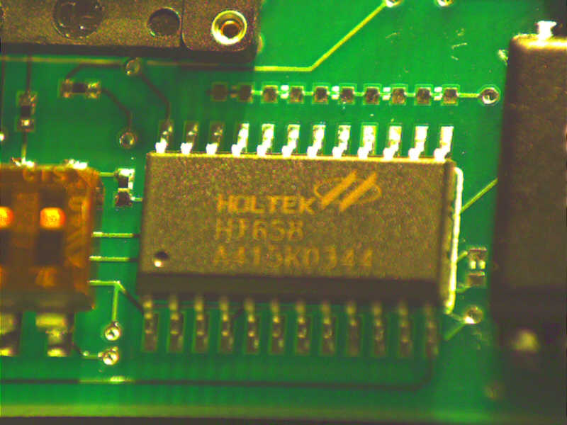
Another cool feature i added in was the LINX 433MHz Long Range receiver module and holtek decoder (pictured). i designed the receiver to be used with 433Mhz 5 button transmitter so therefore 5 channels go from the Decoder to the stamp. look closely at the 4 position dipswitch because 4 channels from the decoder are optional... meaning if you only want to use one data channel from the decoder then turn all 4 switches off and now you can use the I/Os from the stamp that would have come from the decoder on the terminal block. there is also an RJ45 port (no jack installed in the pic). this is used for direct cable connection from other proto baords. i like using RJ45 cable because it is nice and neat. just becareful of the connections because power and ground is also on the connector.
I see a lot of use out of this board in my future halloween projects.
I can't say how long I have been working on this project. Well its finally done. I present to you my RFEFX board. i never really was a BS1 person, no offense parallax, I like my BS2's. the board has many features that some of you may like or may not like.... its your opinion.
Let see... let me start by saying, I dislike Bread Boards, so this was designed not to utilize them.
I was tired of the Serial connection so using a FTDI FT232RL chip (from Parallax) I eliminated the serial. I also wanted direct terminal connectivity to the BS2 (I use SX version) so the terminal blocks were a must. i also wanted the capability of LEDs, so I put them in but there in line with a 10 position dipswitch (the LEDs are not installed in the picture). I use 0805 Surface mount LEDs for my board.
Another cool feature i added in was the LINX 433MHz Long Range receiver module and holtek decoder (pictured). i designed the receiver to be used with 433Mhz 5 button transmitter so therefore 5 channels go from the Decoder to the stamp. look closely at the 4 position dipswitch because 4 channels from the decoder are optional... meaning if you only want to use one data channel from the decoder then turn all 4 switches off and now you can use the I/Os from the stamp that would have come from the decoder on the terminal block. there is also an RJ45 port (no jack installed in the pic). this is used for direct cable connection from other proto baords. i like using RJ45 cable because it is nice and neat. just becareful of the connections because power and ground is also on the connector.
I see a lot of use out of this board in my future halloween projects.
800 x 600 - 196K
800 x 600 - 213K
800 x 600 - 233K

14K
Comments
·· Very nice!· Do you have a schematic for the board?· Any code for it?
▔▔▔▔▔▔▔▔▔▔▔▔▔▔▔▔▔▔▔▔▔▔▔▔
Chris Savage
Parallax Tech Support
csavage@parallax.com
here is the Schematic.... Please note that in the schematic there are 2 usb busses... however, one usb bus is for my Specially designed 4x20 LCD module. the module is sold at parallax but i replaced the 3 pin header with a usb header. this allows nice and neat connectivity between the LCD and the Board.
Let me know if there are any questions.
Post Edited (Gary D.) : 2/9/2006 7:05:27 PM GMT
·· Thanks for posting that.· I know more than a few people will be interested in seeing how you implemented the USB sections.· Where did you have the PCB made?
▔▔▔▔▔▔▔▔▔▔▔▔▔▔▔▔▔▔▔▔▔▔▔▔
Chris Savage
Parallax Tech Support
csavage@parallax.com
PCB's were done at Advanced Circuits (www.4pcb.com).
here is a sample code to use this board as a launch pad for a model rocket. this is assuming a relay is connected to P15. in this code we utilize the LINX 5 button RF transmitter (433Mhz) and the correct sequence of buttons must be pressed (1,2,3,4,5) for added false trigger security. Also a time delay will reset the code if you fail to complete the sequence.
for information on how model rockets work Click here
' {$STAMP BS2sx}
' {$PBASIC 2.5}
'//////////////////////////////////////////////
'// RF MODEL ROCKET CONTROLLER //
'/////////////////////////////////////////////
time VAR Word
reset:
LOW 15
main:
IF IN1 = 1 THEN two
GOTO main
two:
FOR time = 0 TO 1000
IF IN2 = 1 THEN three
next
GOTO reset
three:
FOR time = 0 TO 1000
IF IN3 = 1 THEN four
next
GOTO reset
four:
FOR time = 0 TO 1000
IF IN4 = 1 THEN five
next
GOTO reset
five:
FOR time = 0 TO 1000
IF IN5 = 1 THEN ignite
next
GOTO reset
Ignite:
HIGH 15
PAUSE 3000
GOTO reset
I see that rather than connecting the HT668's pins directly to the BS2's pins, you've put a resister between each.
What is the purpose of these?
And what is the value of these?
And most importantly, how do you calculate the value of these from the datassheets of the HT668 and the BS2?
Get_Sequence:
· LOW LaunchCtrl
· idx = 1
· timer = 1000
· DO
··· IF (INS.LOWBIT(idx) = 1) THEN······· ' current button pressed?
····· idx = idx + 1······················' yes, update pointer
······timer =·1000······················ ' reload for next button
··· ENDIF
··· timer = timer - 1····················'·decrement timer
··· IF (timer = 0) THEN Get_Sequence···· ' if expired, restart
· LOOP UNTIL (idx = 6)···················' keep trying until all pressed·
Ignite:
· HIGH LaunchCtrl
· PAUSE 3000
· GOTO Get_Sequence
▔▔▔▔▔▔▔▔▔▔▔▔▔▔▔▔▔▔▔▔▔▔▔▔
Jon Williams
Applications Engineer, Parallax
Post Edited (Jon Williams (Parallax)) : 1/31/2006 6:15:36 PM GMT
As for your question Jdege,
the Decoder is an HT658 3^18 series decoders. Which corresponds to the HT640 Encoder in the Linx 5 button transmitter.
the outputs of the decoder are treated as hooking up a button to the stamp...
each I/O pin is tied to ground via 10k resistor... and 220 ohms is fed from the decoder to the stamp..
this ensures the stamps pin is kept low untill you press the corresponding button on the transmitter.
Hope this helps.
Gary D.
As for the 220 ohm resistor between the two pins - is that there primarily as a current limiter?
low voltage.
as far as the 220... its just a safety precaution. So you are correct they are current limiting resistors. but they can easily be
substituted for 0 ohm resistors if need be.
▔▔▔▔▔▔▔▔▔▔▔▔▔▔▔▔▔▔▔▔▔▔▔▔
Jon Williams
Applications Engineer, Parallax
Is there something I should be seeing on the datasheet that indicates that this is necessary? Or is it always necessary when tying a CMOS output to a BS2 input pin? Or is it sometimes necessary and sometimes not, and not documented anywhere?
you could very well leave out the 10ks. i just have them for accuracy.
the only time i received holtek error was when my projects were mounted on a bread board. maybe the Capacitance of the bread
board was enough for Malfunction. who knows. I will do some tests this weekend to see if there is a difference.
Here is a Question for you... why are you so concerned about the resistors of the Holtek? wouldn't you rather have resistors for
safety then not have them and destroy something?
Gary D.
Programming the things I have no problem with. Figuring out how to connect things is sometimes an issue.
I've just finished a little project connecting a Basic Stamp to one of Parallax's 418MHz keyfob receivers, flipping a couple of relays. I wired the pins straight. It's been working, except that I'm not sure that the battery life is what I'd hoped for.
When I saw your project, it looked like you were doing something very similar, but you'd added the resisters to those connections.
I wondered why. Whether they were necessary, and what sort of situation would drive the design decision to use them.
I've found a lot of simple sample apps for the BS2 - some with quite good explanations of how they work. But not many that discuss why they were designed in the way they were.
▔▔▔▔▔▔▔▔▔▔▔▔▔▔▔▔▔▔▔▔▔▔▔▔
Jon Williams
Applications Engineer, Parallax
I on the other hand am a Engineer for a Wireless company. We sometimes place resistors to protect Integrated circuits and limit current. by looking at the Button configuration in the Stamp manual it states that resistor is used to limit current flow to the pin. all you want to see when using a button is the State of the pin. tying the pin to a ground with a 10k resistor ensures it is grounded regardless if the decoder is floating or grounded. When the Decoder goes high it takes the least resistance path and makes the I/O pin to the stamp High. as i said before, I treat all inputs as a button configuration to ensure steady operation.
do you think you would benefit from my Board?
the're dying to get build....
▔▔▔▔▔▔▔▔▔▔▔▔▔▔▔▔▔▔▔▔▔▔▔▔
There are 10 kinds of people....
Those who know binary and those who Don't.
My intent is to wire it into my doorbell circuit so as to allow me to ring the bells remotely, or even to program the BS2 to ring them at random intervals.
The goal is to condition my dog to ignore the doorbell - to have the door ring and have nobody there and nobody do anything.
What I have will serve for that. And might find some use with the Christmas decorations.