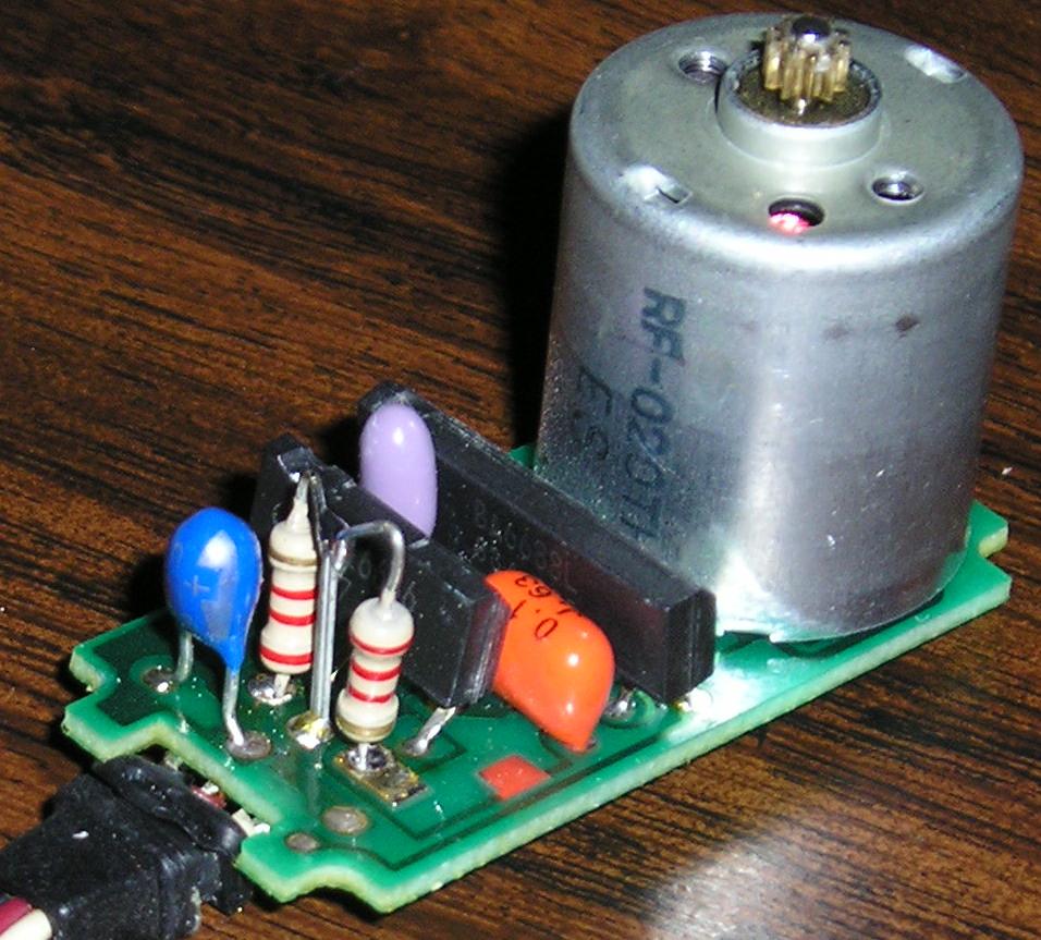
Futaba S148 not responding as expected.
Everywhere I look, people are modifying servos and getting them to spin in one direction and then another direction depending on the pulse.
I must be doing something VERY wrong becuase I can only get mine to spin clockways.
Here is the simple code I am running for testing:
If this snip look familure its because its straight out of the Standard Servo PDF. I have even attempted to widen the range up to 2000 and down to 1.
As for modifying the servo, I have done two things. Keep in mind this is a Futaba FP-S148 servo.
First I just took out·the little plastic clip out that turned the pot and manualy adjusted it to center... I still could not get the servo to go counter clockwise. (based on the code above).
Second, I took the pot out of the picture and added two resistors (2.2k each). I kept the center leg of the pot and replaced the outside legs with the resistors. Tried the above code again... and still had no luck.
Any one have ideas?
I have searched... and found that most of what is suggested I have attempted in one form or another... but by all means, point out my wrong doings.
▔▔▔▔▔▔▔▔▔▔▔▔▔▔▔▔▔▔▔▔▔▔▔▔
0011010000110010
Nitrohawk
I must be doing something VERY wrong becuase I can only get mine to spin clockways.
Here is the simple code I am running for testing:
Servo_pin CON 14 'I/O pin that is connected to servo
temp VAR Word 'Work space for FOR NEXT


start:
DEBUG "start 200 - 1200", CR
FOR temp = 200 TO 1200
  PULSOUT Servo_pin,temp
  PAUSE 50
NEXT

PAUSE 2000

DEBUG "start 1200 - 200", CR
FOR temp = 1200 TO 200
  PULSOUT Servo_pin,temp
  PAUSE 50
NEXT

END
If this snip look familure its because its straight out of the Standard Servo PDF. I have even attempted to widen the range up to 2000 and down to 1.
As for modifying the servo, I have done two things. Keep in mind this is a Futaba FP-S148 servo.
First I just took out·the little plastic clip out that turned the pot and manualy adjusted it to center... I still could not get the servo to go counter clockwise. (based on the code above).
Second, I took the pot out of the picture and added two resistors (2.2k each). I kept the center leg of the pot and replaced the outside legs with the resistors. Tried the above code again... and still had no luck.
Any one have ideas?
I have searched... and found that most of what is suggested I have attempted in one form or another... but by all means, point out my wrong doings.

▔▔▔▔▔▔▔▔▔▔▔▔▔▔▔▔▔▔▔▔▔▔▔▔
0011010000110010
Nitrohawk


Comments
Setup:
· LOW Servo
Main:
· FOR pos = 500 TO 1000 STEP 10
··· FOR idx = 1 TO 3
····· PULSOUT Servo, pos
····· PAUSE 20
··· NEXT
· NEXT
· GOTO Main
Note the timing and refresh values -- I'm not sure where you got your numbers but they don't make sense to me.· You need to refresh the servo about 50 times per second, that equates to a 20 ms delay between pulses.· I hope this helps you get back on track.
▔▔▔▔▔▔▔▔▔▔▔▔▔▔▔▔▔▔▔▔▔▔▔▔
Jon Williams
Applications Engineer, Parallax
Since reseting over and over causes a series of pulses, you get rotation.
That would explain yours behavior.
Alternatively, you may have shorted out something and created a low power condition in that manner. It would also explain why changes in software code apparently have no effect on the behavior.
I had a low battery and both my servos on another manufacture's wheeled bot started to spin in the same direction. The result is tight circles and nothing else.
Removing the tab and using two resistors to make a symetrical voltage divider are right.· Personally, I prefer to keep the pot, but disengage its linkage.· Then I can actually adjust the value to 'center' to what I want.·
It is also possible that one of your resistors is shorted and creating an asymetrical response, but I am not sure how software would responsd.
▔▔▔▔▔▔▔▔▔▔▔▔▔▔▔▔▔▔▔▔▔▔▔▔
"When all think alike, no one is thinking very much.' - Walter Lippmann (1889-1974)
······································································ Warm regards,····· G. Herzog [noparse][[/noparse]·黃鶴 ]·in Taiwan
Post Edited (Kramer) : 1/30/2006 11:39:37 AM GMT
True, but very confusing and misleading. "you can get them to spin by <Causing an INADVERTENT> low battery < condition which will > reset the microprocessor."
And you can easily see if this is happening if you put a "DEBUG [noparse][[/noparse]"I have reset.", 13]" message at the start of your code.
Otherwise, you MUST adjust code for the type of processor, as the PULSOUT values are different.
·· Must be a matter of context.· I took Kramer to mean that if you were experiencing a brownout condition you might inadvertantly generate a pulse causing the servo to go only one way, since it was restarting.· =|
▔▔▔▔▔▔▔▔▔▔▔▔▔▔▔▔▔▔▔▔▔▔▔▔
Chris Savage
Parallax Tech Support
csavage@parallax.com
The chip I am using is the BS2.
The snip of code I used came from this document:
http://www.parallax.com/dl/docs/prod/motors/stdservo.pdf
I am also sure the battery pack (4 AA's) is fully charged using my DMM.
Just to make sure im not going batty, the stripes on the resistor is Red, Red, Red, Gold. That, if I am not mistaken is 2.2k ohms, right?
Jon, Thanks for the suggested code. I will be sure to check that out this evening.
Setup:
  LOW Servo

Main:
  FOR pos = 500 TO 1000 STEP 10
    FOR idx = 1 TO 3
      PULSOUT Servo, pos
      PAUSE 20
    NEXT
  NEXT
  GOTO Main
▔▔▔▔▔▔▔▔▔▔▔▔▔▔▔▔▔▔▔▔▔▔▔▔
0011010000110010
Nitrohawk
A 2.2k resistor would be Red-Red-Red. Red-Red-Yellow would be 220k.
▔▔▔▔▔▔▔▔▔▔▔▔▔▔▔▔▔▔▔▔▔▔▔▔
Jon Williams
Applications Engineer, Parallax
▔▔▔▔▔▔▔▔▔▔▔▔▔▔▔▔▔▔▔▔▔▔▔▔
0011010000110010
Nitrohawk