

Electric Lock and Grab System Time (Help)
 Goten
Posts: 70
Goten
Posts: 70
·Hello,
······
···· I need some help with a system that i am developing,
1.-·I need to know that if it's posible to connect an electric or an electricmagnetic Lock to a BS2,·just on/off
2.- And If someone knows the code (algorithm) to grab the system time on Pbasic and Debug it.
As u see , the idea is to develop an access control.·
Best Regards
GoTeN
▔▔▔▔▔▔▔▔▔▔▔▔▔▔▔▔▔▔▔▔▔▔▔▔
Best Regards from Chile
Goten
Envio editado por (Goten) : 1/30/2006 2:27:10 AM GMT
284 x 324 - 7K
Comments
http://www.parallax.com/dl/docs/cols/nv/vol1/col/nv6.pdf
The BASIC Stamp doesn't have "system time" like a PC; you'll need to connect an RTC (real time clock) chip for that.· There are several available, and we have code for them.· This thread gives a lot of detail about the popular DS1302:
http://forums.parallax.com/showthread.php?p=531080
And, finally, here's an article I wrote in N&V that shows how to create a digital lock program using a rotary encoder:
http://www.parallax.com/dl/docs/cols/nv/vol6/col/nv127.pdf
▔▔▔▔▔▔▔▔▔▔▔▔▔▔▔▔▔▔▔▔▔▔▔▔
Jon Williams
Applications Engineer, Parallax
and for the lock, i just need to know if it's posible to connect a 12V lock to a basic stamp, i know that i only can use 5V, but maybe some of you could have a diagram·of a·driver·or something. On parallax should have locks.
Best Regards
Goten
On our RS-232 AppMod page we have a VB project attached those shows how you can connect the BASIC Stamp to a PC application.· It's not using the programming port, but that change is pretty easy to make if that's what you want to use.
http://www.parallax.com/detail.asp?product_id=29120
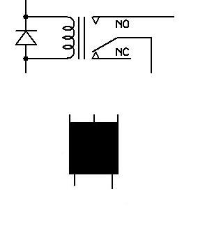
You cannot connect a 12-volt device directly; you'll need an interface -- like the one I've attached (sorry,·forgot to attach to my original post).· The schematic shows a relay; that's where you would connect your lock (spec that transistor to handle device's current properly).
▔▔▔▔▔▔▔▔▔▔▔▔▔▔▔▔▔▔▔▔▔▔▔▔
Jon Williams
Applications Engineer, Parallax
thanx
▔▔▔▔▔▔▔▔▔▔▔▔▔▔▔▔▔▔▔▔▔▔▔▔
Best Regards from Chile
Goten
▔▔▔▔▔▔▔▔▔▔▔▔▔▔▔▔▔▔▔▔▔▔▔▔
Chris Savage
Parallax Tech Support
csavage@parallax.com
But i have some doubt, for example how to connect the led A or B (second image)
and if the Relay it's ok (third image), i have 5 pins and i really don't know too much about, electronic... yes·neither electricity·nor informatic... but i'm learning...
▔▔▔▔▔▔▔▔▔▔▔▔▔▔▔▔▔▔▔▔▔▔▔▔
Best Regards from Chile
Goten
▔▔▔▔▔▔▔▔▔▔▔▔▔▔▔▔▔▔▔▔▔▔▔▔
Chris Savage
Parallax Tech Support
csavage@parallax.com
▔▔▔▔▔▔▔▔▔▔▔▔▔▔▔▔▔▔▔▔▔▔▔▔
1 + 1 = Window
/\/\/\/\/\/\/\/\/\/\/\/\/\/\/\/\/\/\/\
0............................................0
0............................................0
0.(Microman171@hotmail.com)..0
0............................................0
0............................................0
\/\/\/\/\/\/\/\/\/\/\/\/\/\/\/\/\/\/\/
Another question, that's the correct order to connect a Transistor? Image attached
thanx for your help...
▔▔▔▔▔▔▔▔▔▔▔▔▔▔▔▔▔▔▔▔▔▔▔▔
Best Regards from Chile
Goten
Envio editado por (Goten) : 1/27/2006 8:54:07 PM GMT
http://www.fairchildsemi.com/ds/MM%2FMMBT2222A.pdf
... if I'm reading the pinout correctly, your outer pins are reversed.
▔▔▔▔▔▔▔▔▔▔▔▔▔▔▔▔▔▔▔▔▔▔▔▔
Jon Williams
Applications Engineer, Parallax
But something is not working....
Please give me a last hand.
an image is attached.. please check it... something must be worng.
▔▔▔▔▔▔▔▔▔▔▔▔▔▔▔▔▔▔▔▔▔▔▔▔
Best Regards from Chile
Goten
▔▔▔▔▔▔▔▔▔▔▔▔▔▔▔▔▔▔▔▔▔▔▔▔
Jon Williams
Applications Engineer, Parallax
On the drawing it says that the relay is 5V. I think he is only using the 12V for the magnetic lock.
The problem I see is that he doesn't have +5V going to the relay coil. I assume it would go to the upper right connection on his drawing. Hmmm, but then the diode would be in backwords...
Bean.
▔▔▔▔▔▔▔▔▔▔▔▔▔▔▔▔▔▔▔▔▔▔▔▔
"SX-Video·Module" Now available from Parallax for only $28.95
http://www.parallax.com/detail.asp?product_id=30012
"SX-Video OSD module" Now available from Parallax for only·$49.95
http://www.parallax.com/detail.asp?product_id=30015
Product web site: www.sxvm.com
"Ability may get you to the top, but it takes character to keep you there."
·
Since you're using a 5v relay I've whipped up a quick schematic for you.· How much current does your relay require to activate?
▔▔▔▔▔▔▔▔▔▔▔▔▔▔▔▔▔▔▔▔▔▔▔▔
Jon Williams
Applications Engineer, Parallax
The circuit idea is afetr the a sensor works, it open the lock. my problem is that the lock works with 12V, and i only could have 5 from the Basic.
It's possible to connect just a Transistor between the basic and the lock?
▔▔▔▔▔▔▔▔▔▔▔▔▔▔▔▔▔▔▔▔▔▔▔▔
Best Regards from Chile
Goten
Also, you might want to read this article: http://www.parallax.com/dl/docs/cols/nv/vol1/col/nv6.pdf
▔▔▔▔▔▔▔▔▔▔▔▔▔▔▔▔▔▔▔▔▔▔▔▔
Jon Williams
Applications Engineer, Parallax
The Solenoid of the schematic it is the lock.
but where should i put the diodo, between + and - of the lock?
▔▔▔▔▔▔▔▔▔▔▔▔▔▔▔▔▔▔▔▔▔▔▔▔
Best Regards from Chile
Goten
▔▔▔▔▔▔▔▔▔▔▔▔▔▔▔▔▔▔▔▔▔▔▔▔
Jon Williams
Applications Engineer, Parallax
loop:
· low 7······ ' Pin 7 low to latch door
' (relay open)
· serin 0,N2400,("OK")·· ' Watch serial input
' until "OK" rec'd.
· high 7······ ' Pin 7 high to unlatch do
' (relay closed).
· pause 5000······ ' Wait 5 seconds.
goto loop······ ' Latch door and resume
' watching serial input.
but i have problems using "N2400" it's an undefined symbol. i'm using a bs2
▔▔▔▔▔▔▔▔▔▔▔▔▔▔▔▔▔▔▔▔▔▔▔▔
Best Regards from Chile
Goten
There are a number of problems with your program. As far as the undefined symbol is concerned, you neglected to put the following coding in your program, which defines that symbol using conditional compilation, depending on the type of Stamp you are using:
/code
#SELECT $STAMP
#CASE BS2, BS2E
T2400 CON 396 ' reader baud rate
TmAdj CON $100 ' x 1.0 (time adjust)
FrAdj CON $100 ' x 1.0 (freq adjust)
#CASE BS2SX
T2400 CON 1021
TmAdj CON $280 ' x 2.5
FrAdj CON $066 ' x 0.4
#CASE BS2P
T2400 CON 1021
TmAdj CON $3C5 ' x 3.77
FrAdj CON $044 ' x 0.265
#CASE BS2PE
T2400 CON 396
TmAdj CON $100 ' x 1.0
FrAdj CON $0AA ' x 0.665
#ENDSELECT
code/
Second, you can't read into a constant, as you have done here (below), and I suspect this is supposed to be a WAIT parameter, in any case:
serin 0,N2400,("OK") ' Watch serial input
It should probably have read as follows, if you are hoping to WAIT for an OK to be transmitted:
SERIN 0, N2400, (WAIT "OK")
The next problem that you have is that after a period of time when "OK" has not been seen, the SERIN statement will time out, and you've made no provision for that. I would suggest you read about the SERIN command in the PBASIC Stamp Manual, or from the PBASIC Help File before you go much further in this hit and miss process. It's really quite simple, if you take a few moments to read and understand it, honestly.
Regards,
Bruce Bates
Post Edited (Bruce Bates) : 1/30/2006 3:20:57 PM GMT
▔▔▔▔▔▔▔▔▔▔▔▔▔▔▔▔▔▔▔▔▔▔▔▔
Jon Williams
Applications Engineer, Parallax
▔▔▔▔▔▔▔▔▔▔▔▔▔▔▔▔▔▔▔▔▔▔▔▔
Best Regards from Chile
Goten
tomorrow i'll post somepicutresS!!!! tyhanx to everybody!!!
thanx Parallax!!!!
▔▔▔▔▔▔▔▔▔▔▔▔▔▔▔▔▔▔▔▔▔▔▔▔
Best Regards from Chile
Goten