Building a Stamp-Lite
Well, after a lot of effort, I finally figured out the minimum number of components needed to build a functioning Basic Stamp II.
My goal of this was to separate a·BASIC Stamp II into three discrete "modules":· A "Programmer used to interface to the Stamp Editor running on the computer; A "Stamp-Lite·that was a functioning Stamp with minimal components; A power·source that provides clean regulated power to both the Stamp-Lite and·"Programmer".
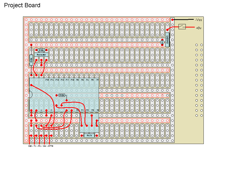
I have finally figured out the "Stamp Lite" circuit.· It is comprised of the following:
1.· Parallax pre-programmed PIC
2.· EEPROM
3.· Resonator
4.· (3) 10k Resistors
5.· (1) 4.7k Resistor
I assembled it on a board from Radio Shack as shown below and in the attached.

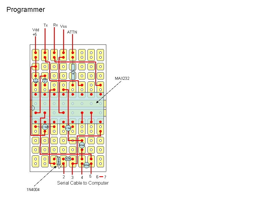
My next step is to build a "Programmer" based on a MAX232... I have a circuit that I cobbled together from a variety of sources, but it doesn't work.· Any ideas on how to build the "Programmer" based on a MAX232?
Here is what I have so far...

I have placed several posts before related to my project, but thought it best to start a new thread since my prior drawings were inaccurate.
Post Edited (Steve Joblin) : 1/22/2006 8:17:27 PM GMT
My goal of this was to separate a·BASIC Stamp II into three discrete "modules":· A "Programmer used to interface to the Stamp Editor running on the computer; A "Stamp-Lite·that was a functioning Stamp with minimal components; A power·source that provides clean regulated power to both the Stamp-Lite and·"Programmer".
I have finally figured out the "Stamp Lite" circuit.· It is comprised of the following:
1.· Parallax pre-programmed PIC
2.· EEPROM
3.· Resonator
4.· (3) 10k Resistors
5.· (1) 4.7k Resistor
I assembled it on a board from Radio Shack as shown below and in the attached.
My next step is to build a "Programmer" based on a MAX232... I have a circuit that I cobbled together from a variety of sources, but it doesn't work.· Any ideas on how to build the "Programmer" based on a MAX232?
Here is what I have so far...
I have placed several posts before related to my project, but thought it best to start a new thread since my prior drawings were inaccurate.
Post Edited (Steve Joblin) : 1/22/2006 8:17:27 PM GMT


Comments
http://www.phanderson.com/stamp/
One of the things you need to remember is that the BASIC Stamp circuit echoes everything that the PC sends to it; you'll need to make this happen with your MAX232 circuit or else the editor will think there's a problem.· It may be as simple as putting a 4.7K between your MAX232-RX out to the MAX232-TX in; this should cause the echo without causing a conflict between the Stamp's Sout pin and the MAX232-RX out pin.
▔▔▔▔▔▔▔▔▔▔▔▔▔▔▔▔▔▔▔▔▔▔▔▔
Jon Williams
Applications Engineer, Parallax
·
·
▔▔▔▔▔▔▔▔▔▔▔▔▔▔▔▔▔▔▔▔▔▔▔▔
Jon Williams
Applications Engineer, Parallax
·· The following schemeatics are the two I were mentioned before.· There are two in a ZIP file.· The first one is a lite version of the OEM BS2 and the second is a lighter version (no reset supervisor/brownout detector).· These should both work fine for you.· I do have a final schematic which is designed to integrate a USB connection (FT232BM/Q) which I will post tomorrow evening.· I need to make two more tests.
▔▔▔▔▔▔▔▔▔▔▔▔▔▔▔▔▔▔▔▔▔▔▔▔
Chris Savage
Parallax Tech Support
csavage@parallax.com
Now onto the Programmer portion... any ideas on how to create a simple version that I can easily build myself? I liked the idea of the MAX232 since it only has a few components... the "version" that is on the OEM has too many resistors and transistors for me to build myself on a prototype board. (I guess I could cut the Stamp OEM board to make it smaller, but I would really like to build it myself.
Al Williams' RS-1 serial adapter is one of the nicer units I've seen, and it's fairly compact. He also offers the board only, if you want to use your own parts.
http://www.awce.com/rs1.htm?PHPSESSID=fe71c0c85380f335b943916f0b5760e8
Regards,
Bruce Bates
·· As pointed out by others there are serial port solutions out there.· Some with more parts, some less.· The main thing you have to keep in mind is that the line I showed pulled high must still be pulled high with the programming circuitry implemented.· Also, there must be loopback as shown in our original schematic.· With the already plentiful serial solutions I am exploring a direct USB connection, currently using our USB2SER.· I should have that information today.
▔▔▔▔▔▔▔▔▔▔▔▔▔▔▔▔▔▔▔▔▔▔▔▔
Chris Savage
Parallax Tech Support
csavage@parallax.com
Post Edited (Steve Joblin) : 1/24/2006 6:25:23 PM GMT
·· Those capacitors prevent certain computers from holding the DTR line HIGH.· When this happens it would normally hold the Stamp in a state of RESET, but the capacitors (Well, one) blocks DC and allows only a pulse to reset the Stamp Module.· That isn't a problem on all machines.· Nonetheless since my schematics deal with the USB port, I don't have to worry about that, so it's not included on my schematics.
▔▔▔▔▔▔▔▔▔▔▔▔▔▔▔▔▔▔▔▔▔▔▔▔
Chris Savage
Parallax Tech Support
csavage@parallax.com
http://forums.parallax.com/showthread.php?p=567989
▔▔▔▔▔▔▔▔▔▔▔▔▔▔▔▔▔▔▔▔▔▔▔▔
Chris Savage
Parallax Tech Support
csavage@parallax.com