Shop OBEX P1 Docs P2 Docs Learn Events
Circuit explanation — Parallax Forums

Circuit explanation

M. KibatM. Kibat Posts: 12
edited 2005-12-15 20:59 in General Discussion
[noparse][[/noparse]Please refer to the attached .jpg file]

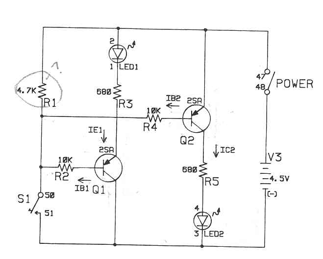
What's the purpose of the R1 resistor in the attached circuit (a simple demo of transistor switches). Is it just to limit the overall current when the POWER and S1 switches are both thrown at the same time? Or is it doing something else that I'm just not seeing?

Thanks!

▔▔▔▔▔▔▔▔▔▔▔▔▔▔▔▔▔▔▔▔▔▔▔▔
M. Kibat
Bloomington, MN
kibatme@visi.com
659 x 529 - 18K

Comments

  • Paul BakerPaul Baker Posts: 6,351
    edited 2005-12-14 23:21
    R1 prevents a short from occuring when switch 1 is closed. When switch 1 is open, the node the base of both transistors is connected to is pulled up to near 4.5V, when the switch is closed, the node is tied directly to ground (turning both transistors on), the 4.7kΩ resistor passes just under 1mA through it.

    ▔▔▔▔▔▔▔▔▔▔▔▔▔▔▔▔▔▔▔▔▔▔▔▔
    ·1+1=10
  • kjennejohnkjennejohn Posts: 171
    edited 2005-12-15 00:25
    Both transistors are PNPs. It takes a NEGATIVE voltage (in this case GROUND) on the BASE to turn the transistor ON.
    After power is applied, with S1 open, R1 biases both transistors OFF. Closing S1 turns both transistors ON, and the LEDs light. Without R1, with S1 open, the transistors would be in an indeterminate state, and chaos would reign! (just kiddin'!)

    Happy holidays!
    kenjj
  • pjvpjv Posts: 1,903
    edited 2005-12-15 00:30
    Hi Kibat;

    The circuit will work if you delete the resistor R1, but it is better for elevated temperatures to have it present.

    The small leakge current from both transistor collectors to their respective bases has a "drain-away" path through this resistor, and also it facilitates the quick dissipation of charge in the base-emitter junctions, thus causing it to switch faster.

    For the penny that it costs, it is just a better way to do things.

    Cheers,

    Peter (pjv)
  • Paul BakerPaul Baker Posts: 6,351
    edited 2005-12-15 15:59
    Peter, I dont see how you could eliminate R1, when the power switch is on and switch 1 is closed, there is a direct low resistance path from the + terminal to the - terminal, thats a short, and a good way to explode the battery or smoke the power supply.

    ▔▔▔▔▔▔▔▔▔▔▔▔▔▔▔▔▔▔▔▔▔▔▔▔
    ·1+1=10
  • BeanBean Posts: 8,129
    edited 2005-12-15 16:19
    Peter means to leave it OPEN not shorted.
    Bean.

    ▔▔▔▔▔▔▔▔▔▔▔▔▔▔▔▔▔▔▔▔▔▔▔▔
    "SX-Video·Module" Now available from Parallax for only $28.95

    http://www.parallax.com/detail.asp?product_id=30012

    "SX-Video OSD module" Now available from Parallax for only·$49.95
    http://www.parallax.com/detail.asp?product_id=30015

    Product web site: www.sxvm.com

    Forget about the past, plan for the future, and live for today.
    ·
  • Paul BakerPaul Baker Posts: 6,351
    edited 2005-12-15 16:37
    If switch 1 is left open, wouldn't it be a non-functional circuit? The 2 pnps would be off (and the LEDs would be off) and to turn them on (via closing switch 1)·would cause a short.

    ▔▔▔▔▔▔▔▔▔▔▔▔▔▔▔▔▔▔▔▔▔▔▔▔
    ·1+1=10
  • pjvpjv Posts: 1,903
    edited 2005-12-15 16:59
    Hi Paul;

    As Bean said, what my post referred to was in omitting the resistor; NOT replacing it with a piece of wire.

    Cheers,

    Peter (pjv)
  • Paul BakerPaul Baker Posts: 6,351
    edited 2005-12-15 17:17
    Ok now I understand, sorry for my confusion.

    ▔▔▔▔▔▔▔▔▔▔▔▔▔▔▔▔▔▔▔▔▔▔▔▔
    ·1+1=10
  • SN96SN96 Posts: 318
    edited 2005-12-15 17:21
    pjv said...
    Hi Paul;

    As Bean said, what my post referred to was in omitting the resistor; NOT replacing it with a piece of wire.

    Cheers,

    Peter (pjv)
    But then you would loose that nice square circuit outline.

    Just kidding smilewinkgrin.gif

    ▔▔▔▔▔▔▔▔▔▔▔▔▔▔▔▔▔▔▔▔▔▔▔▔
    Mike

    ·
  • M. KibatM. Kibat Posts: 12
    edited 2005-12-15 20:59
    pjv said...
    Hi Kibat;

    The circuit will work if you delete the resistor R1, but it is better for elevated temperatures to have it present.

    The small leakge current from both transistor collectors to their respective bases has a "drain-away" path through this resistor, and also it facilitates the quick dissipation of charge in the base-emitter junctions, thus causing it to switch faster.

    For the penny that it costs, it is just a better way to do things.

    Cheers,

    Peter (pjv)
    Thanks! I had verified the circuit worked without the resistor -- hence my question. Your additional explanation for its purpose makes sense...

    ▔▔▔▔▔▔▔▔▔▔▔▔▔▔▔▔▔▔▔▔▔▔▔▔
    M. Kibat
    Bloomington, MN
    kibatme@visi.com
Sign In or Register to comment.