

SX28 Supply Current
 Guenther Daubach
Posts: 1,321
Guenther Daubach
Posts: 1,321
Hi SXers,
today, I was curious enough to measure the supply current drawn by an SX28 under various conditions. I have compiled the results in graphs that are attached to this post.
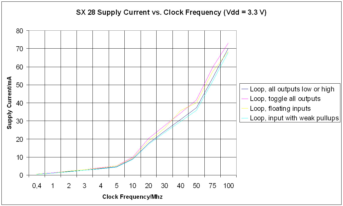
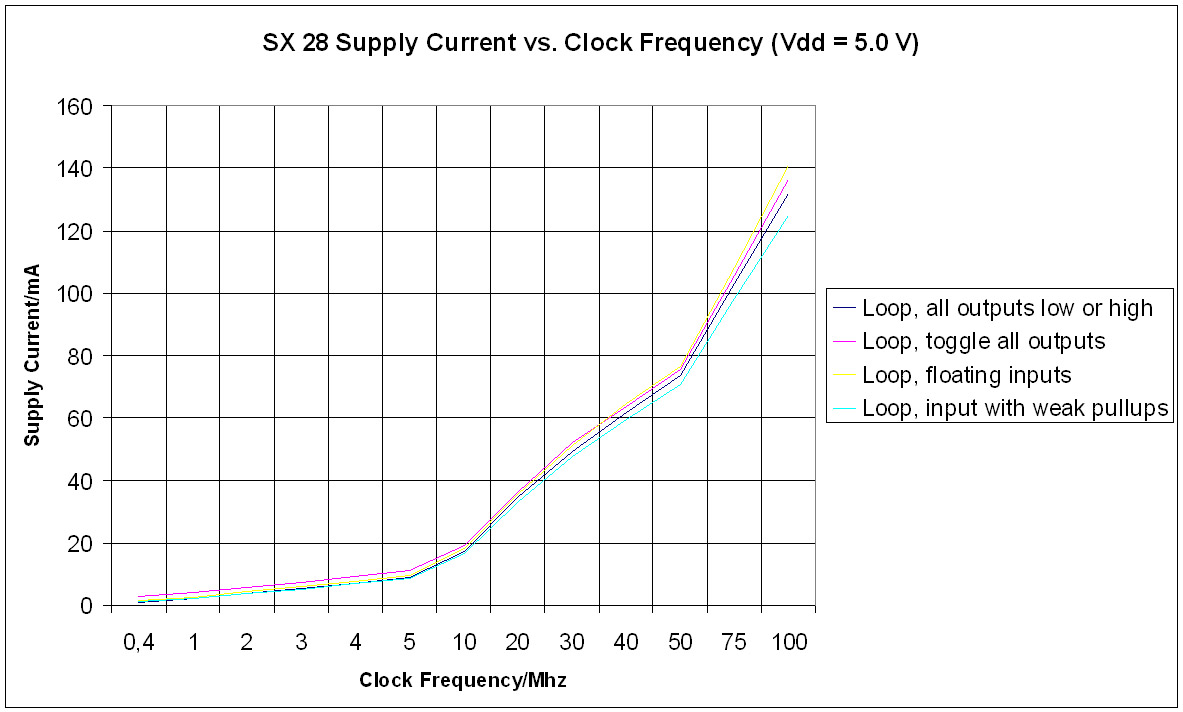
I have performed two sets of measurements, one at 5V and one at 3.3V Vdd. Within each set, I performed four rows with different programs running on the SX:
1. Loop, all outputs low or high: At initialization, all port pins are set to outputs. Then the program enters into an endless loop. The supply current did not remarkably change if the outputs were all set to high, or low level, so I only recorded one row with all outputs set to low.
2. Loop, toggle all outputs: At initialization, all port pins are set to outputs. Then the program enters into a loop where all output pins are periodically toggled between high and low as fast as possible.
3. Loop, floating inputs: At initialization, all port pins are set to inputs with no external components attached to the pins, and internal weak pull-up resistors not enabled. Then the program enters into an endless loop.
4. Loop, inputs with weak pull-ups: At initialization, all port pins are set to inputs with no external components attached to the pins, and internal weak pull-up resistors enabled. Then the program enters into an endless loop.
As you can see from the diagrams, the supply current is a function of the clock frequency, and it seems as if it is an almost linear function. The supply current is also a function of the supply voltage. Clocked at 50 MHz, the SX28 draws about 40mA at 3.3V Vdd but about 70mA when Vdd is 5V.
Thus, the SX28 power consumption can be as low as 1.7mW (400kHz, 3.3V) but also as high as 705mW (100MHz, 5.0V).
You may wonder why there is such a great difference in power consumption. The SX28 is built of thousands of logical cells where each of them can assume two states. Let's think of each logical cell being a capacitor that may either be charged, or discharged in order to represent the two logical states. An "ideal" chip would consist of "ideal" capacitors (i.e. no leakage), and of "ideal" conductors (i.e. no resistance). Unfortunately, this is not reality - capacitors will leak (i.e. some load is lost, and must be "refilled"). Also, the conductors have a resistance, i.e. whenever a logical cell is charged or discharged a current flows through its conductors with their resistance causing a voltage drop. Voltage drop * current means power converted to heat.
This explains why the supply current drawn by the SX (and the dissipated power) is a function of the clock frequency and the supply voltage. The faster the SX is clocked, the more state changes of logical cells happen within a period of time, and the higher the supply voltage is, the higher the voltage drop across the internal conductors will be, resulting in a higher power dissipation (heat).
Although the difference in supply current between the four test rows at each supply voltage is not that big, it confirms what I have mentioned before. Row 1 with static outputs does not change the logical cells in the output registers, where this is periodically the case in Row 2. This is why the current is slightly higher for Row 2, compared to Row 1.
Actually, the results for Row 3 are not very exact. Due to the floating inputs, it is most likely that the input states randomly change between high and low. I could confirm this by bringing a finger close to the SX chip. This made the supply current noticeably increase. Obviously, bringing my finger close to the chip did couple enough noise into the floating input pins that they changed their states more often.
With the internal weak pull-up resistors enabled for Row 4, the "finger test" did not influence the current drawn anymore.
Although this has been mentioned in the forum more than once, let me repeat it again: Unused I/O pins should either be defined as outputs, initialized to either high or low level, or as inputs with either the internal weak pull-up resistor enabled, or an external pull-up, or pull-down resistor attached.
A final remark: I did all these tests with just one SX28 AC/DP "out of the box". When you repeat these measurements, results may possibly be different due to component tolerances. For all tests, I used an SX-Key as clock generator, with the SX-Key and the SX28 powered from separate power sources, i.e. with the SX-Key always powered from a 5V supply, and the SX28 from a 5V or 3.3V supply with the current meter hooked up in the SX28 supply loop only.
As a "side effect", my test setup did also prove that it is possible to program/clock/debug an SX target system powered with 3.3V when you power the SX-Key from a separate 5V supply.
Although results for other SX devices may be different this should give you a rule of thumb, and I hope this information will be useful for you.
▔▔▔▔▔▔▔▔▔▔▔▔▔▔▔▔▔▔▔▔▔▔▔▔
Greetings from Germany,
G
today, I was curious enough to measure the supply current drawn by an SX28 under various conditions. I have compiled the results in graphs that are attached to this post.
I have performed two sets of measurements, one at 5V and one at 3.3V Vdd. Within each set, I performed four rows with different programs running on the SX:
1. Loop, all outputs low or high: At initialization, all port pins are set to outputs. Then the program enters into an endless loop. The supply current did not remarkably change if the outputs were all set to high, or low level, so I only recorded one row with all outputs set to low.
2. Loop, toggle all outputs: At initialization, all port pins are set to outputs. Then the program enters into a loop where all output pins are periodically toggled between high and low as fast as possible.
3. Loop, floating inputs: At initialization, all port pins are set to inputs with no external components attached to the pins, and internal weak pull-up resistors not enabled. Then the program enters into an endless loop.
4. Loop, inputs with weak pull-ups: At initialization, all port pins are set to inputs with no external components attached to the pins, and internal weak pull-up resistors enabled. Then the program enters into an endless loop.
As you can see from the diagrams, the supply current is a function of the clock frequency, and it seems as if it is an almost linear function. The supply current is also a function of the supply voltage. Clocked at 50 MHz, the SX28 draws about 40mA at 3.3V Vdd but about 70mA when Vdd is 5V.
Thus, the SX28 power consumption can be as low as 1.7mW (400kHz, 3.3V) but also as high as 705mW (100MHz, 5.0V).
You may wonder why there is such a great difference in power consumption. The SX28 is built of thousands of logical cells where each of them can assume two states. Let's think of each logical cell being a capacitor that may either be charged, or discharged in order to represent the two logical states. An "ideal" chip would consist of "ideal" capacitors (i.e. no leakage), and of "ideal" conductors (i.e. no resistance). Unfortunately, this is not reality - capacitors will leak (i.e. some load is lost, and must be "refilled"). Also, the conductors have a resistance, i.e. whenever a logical cell is charged or discharged a current flows through its conductors with their resistance causing a voltage drop. Voltage drop * current means power converted to heat.
This explains why the supply current drawn by the SX (and the dissipated power) is a function of the clock frequency and the supply voltage. The faster the SX is clocked, the more state changes of logical cells happen within a period of time, and the higher the supply voltage is, the higher the voltage drop across the internal conductors will be, resulting in a higher power dissipation (heat).
Although the difference in supply current between the four test rows at each supply voltage is not that big, it confirms what I have mentioned before. Row 1 with static outputs does not change the logical cells in the output registers, where this is periodically the case in Row 2. This is why the current is slightly higher for Row 2, compared to Row 1.
Actually, the results for Row 3 are not very exact. Due to the floating inputs, it is most likely that the input states randomly change between high and low. I could confirm this by bringing a finger close to the SX chip. This made the supply current noticeably increase. Obviously, bringing my finger close to the chip did couple enough noise into the floating input pins that they changed their states more often.
With the internal weak pull-up resistors enabled for Row 4, the "finger test" did not influence the current drawn anymore.
Although this has been mentioned in the forum more than once, let me repeat it again: Unused I/O pins should either be defined as outputs, initialized to either high or low level, or as inputs with either the internal weak pull-up resistor enabled, or an external pull-up, or pull-down resistor attached.
A final remark: I did all these tests with just one SX28 AC/DP "out of the box". When you repeat these measurements, results may possibly be different due to component tolerances. For all tests, I used an SX-Key as clock generator, with the SX-Key and the SX28 powered from separate power sources, i.e. with the SX-Key always powered from a 5V supply, and the SX28 from a 5V or 3.3V supply with the current meter hooked up in the SX28 supply loop only.
As a "side effect", my test setup did also prove that it is possible to program/clock/debug an SX target system powered with 3.3V when you power the SX-Key from a separate 5V supply.
Although results for other SX devices may be different this should give you a rule of thumb, and I hope this information will be useful for you.
▔▔▔▔▔▔▔▔▔▔▔▔▔▔▔▔▔▔▔▔▔▔▔▔
Greetings from Germany,
G
1183 x 712 - 109K
1183 x 712 - 108K
Comments
Very interesting stuff. Seeing the difference in supply current between 3.3v and 5v makes me want to consider converting one of my projects from 5 to 3.3 for the power savings. I was always curious about the power consumption of the SX versus frequency, but never took the time to find out. I'm glad you did because it saves me a lot of time!
thanks, PeterM
Please put these graphs into the new Parallax SX datasheet.
To be honest, I did not really consider driving SX systems @ 3.3V so far but because of a special reason (Peter, you should know), I had to do some tests at 3.3V. For me, one important result was to make sure that an SX can be powered @ 3.3V with the SX-Key separately powered @ 5V. Thus it is possible to program/debug/clock 3.3V target devices with an SX-Key as long as the Key "sees" 5V Vdd.
Another important result was the remarkably lower power consumption at higher clock rates with just 3.3V supply. I did not do any stress tests but it seems to me that an SX can be clocked with 75 or even 100MHz when powered with 3.3V w/o running into heat problems.
William,
well, I'm not working on the new SX datasheets but I'm pretty sure Parallax will include graphs like this, and they may use mine if they like.
▔▔▔▔▔▔▔▔▔▔▔▔▔▔▔▔▔▔▔▔▔▔▔▔
Greetings from Germany,
G
▔▔▔▔▔▔▔▔▔▔▔▔▔▔▔▔▔▔▔▔▔▔▔▔
John J. Couture
San Diego Miramar College
I'm not a math wizz at all - I'm glad when Excel can handle the job for me, and I love my HP48 RPN calculator (5 ENTER 2 *)
Bean,
at least, this is what the results of my measurements are. Actually, the differences between unused pins configured as outputs with a constant level (low or high), or as inputs with pull-ups or pull-downs is not that dramatic. The only important thing is to keep such pins "quiet".
BTW, I forgot to mention in my original post that I did not measure currents with an oscillator device attached, like a resonator or crystal. I only used the SX-Key to comfortably change the clock frequencies. When I have the time, I'll check the power consumption with other clock sources, and post the results if they make a remarkable difference.
▔▔▔▔▔▔▔▔▔▔▔▔▔▔▔▔▔▔▔▔▔▔▔▔
Greetings from Germany,
G
As you know, I have been very interested in the 3.3 volt applications because it really enables many more battery operated devices at remote sites and with the possiblity of solar battery recharge.
To restate, you are saying that you can easily program an SX-28 running at 3.3volts, BUT ONLY IF THE SX-KEY or SX-BLITZ is supplied with 5.0 volts.
The reason I clarifying is that I was thinking of building a 3.3volt board. Ease of programing could be integrated.
It seems that it would be very convienent to provide a 3 pin socket to plug in a 5 volt regulator during programing. Later I could remove the 5.0 regulator along with the SX-Key as a means to conserve power.
Alternatively I suppose I could keep the regulator solder into the board and have a jumper that provides or removes power to the regulator.
This is all wonderful news. Do you have any suggestions for the best family of logic to use at 3.3 volts?
▔▔▔▔▔▔▔▔▔▔▔▔▔▔▔▔▔▔▔▔▔▔▔▔
"When all think alike, no one is thinking very much.' - Walter Lippmann (1889-1974)
······································································ Warm regards,····· G. Herzog [noparse][[/noparse]·黃鶴 ]·in Taiwan
There are loads of logic families for 3.3V - depends how fast you need to go. Have a look at http://www.ti.com for selection tables - but expect not to be able to find every device you want in most families - the oddball stuff gets hard to find, but thingslikeoctal latches and buffers are available in pretty much every flavour.
Also, be warned that many of the newer families are only available in small surface mount packages. DIP's pretty much dead...
Steve
As long as we're on the subject of low power, does anyone know what the minimum input current is that would be detectable by an SX input pin?
▔▔▔▔▔▔▔▔▔▔▔▔▔▔▔▔▔▔▔▔▔▔▔▔
I wonder if this wire is hot...
when I did the 3.3V power consumption measurements, I had to supply the SX28 with 3.3V for the 3.3V rows, of course. On the other hand, the SX-Key does not work at this low voltage (mostly because of the clock generator used on-board the SX-Key which is only specified for 5V). Therefore, I had mounted the SX under test on a breadboard, and not on an SX Tech Board, or on the PDB. This made it easy for me to hand-wire the SX28 and the SX-Key using split supply voltages. My only concern was if it could do any harm to the SX powered at 3.3V with the SX-Key connected to the OSC1 and OSC2 pins feeding in 5V signals. Obviously, this was not the case, as both, the SX-Key and the SX are still in good operating shape
When you only want to use the SX-Key/Blitz for in-system programming, it might be an idea to use a socket for the regulator, allowing you to insert a 5V type during programming. On the other hand, you must keep in mind that all components on the board will be powered @ 5V in this case, so this might cause trouble if you have other componts on the board that only allow for a max. of 3.3V supply.
I also agree with Steve that sockets are always a source of trouble, so I would avoid them here. As Steve mentioned, it is always possible to feed in an external higher voltage, leaving the 3.3V regulator in its place. Again, this implies that all on-board components are powered at 5V in this case, not just the SX.
Instead, you could add a two-pin header, one pin connected to the SX-Key's Vdd header pin, and the other conncted to the board's Vdd signal. When you supply the board with 5V, just attach a jumper to this header, and the SX-Key will be supplied from the board's 5V, as usual. When the board is supplied with 3.3V, remove the jumper, and connect the jumper pin attached to the SX-Key's Vdd pin to an external 5V supply (with its minus pole connected to some Vss point on the board). This allows you to run all board components at 3.3V, and to use the SX-Key powered at 5V for programming, clocking and debugging.
▔▔▔▔▔▔▔▔▔▔▔▔▔▔▔▔▔▔▔▔▔▔▔▔
Greetings from Germany,
G
SX input pins actually are not current-controlled but voltage-controlled. An SX input with no internal pull-up activated has a realtively high impedance. I have never measured it but I assume it quite high in the > 10 MOhm area. This means you could feed in a high or low signal into an SX input via a relatively large resistor, which still would change the input's logical state - but - please don't do it. This will dramatically increase the noise immunity of the input. Actually, this comes close to leaving unused inputs open and floating.
In general, there are three possible methods, how an SX input can be controlled:
1. Actively pulled high (think of an SPST switch, connecting the pin to Vdd, or leaving it open). To avoid a floating input when the switch is open, you will need to connect a pull-down resistor between the input and Vss. When the switch is open, almost no current will flow, and when it is closed the current depends on Vdd and the resistor. With 5V Vdd and a a 10 kOhm resistor, the current would be 0.5 mA.
2. Actively pulled low (think of an SPST switch, connecting the pin to Vss, or leaving it open). To avoid a floating input when the switch is open, you will need to connect a pull-up resistor between the input and Vdd. When the switch is open, almost no current will flow, and when it is closed the current again depends on Vdd and the resistor, as before.
3. Actively pulled high or low (think of a SPDT switch, connecting the pin to either Vdd, or Vss). In this case, no pull-up or pull-down resistors are required, as the input is always connected to a defined level via the switch.
Similar to mechanical switches the same is true for electronic components driving SX inputs. A single transistor or a photocoupler may be used to pull the input high or low (methods 1 or 2), or an IC output (TTL or CMOS) may drive the pin high or low (method 3).
Whatver method you may use, it is always important to avoid SX inputs "hanging in the air", i.e. having them float. Even small static charges/discharges may change the logical level on an input port read causing unpredictable results.
▔▔▔▔▔▔▔▔▔▔▔▔▔▔▔▔▔▔▔▔▔▔▔▔
Greetings from Germany,
G
What I am thinking is akin to what Guenther did.
Provide 5.0V to the SX-Key alone and leave the other 3.3V circuit intact. Having an 'on-board' 5 volt regulator for programing, powering only the SX-Key·when only programing [noparse][[/noparse]seems a bit silly].
Alternatively I suppose you could just program from the SX-Key by providing the 2 wires to the OSC and providing +5.0 away from the circuit board.
This option might be the best as you would not have to populate the board with more connectors and a special programing configuration. As long as the SX-Key can tolerate using 2-3 inch 'jumper wires' to connect, all is well. One interesting implication is you reduce the programing connection to just 2 pins on board.
And BTW, I thought the SX programing mode actually went to something higher than the +5 in order to bypass the oscillator and to shift the SX into a programing mode. WAS I IMAGINING THINGS? It wouldn't be the first time.
I do understand that the clock on the SX-Key requires the +5 volts and is central to the need for that voltage.·
▔▔▔▔▔▔▔▔▔▔▔▔▔▔▔▔▔▔▔▔▔▔▔▔
"When all think alike, no one is thinking very much.' - Walter Lippmann (1889-1974)
······································································ Warm regards,····· G. Herzog [noparse][[/noparse]·黃鶴 ]·in Taiwan
Post Edited (Kramer) : 12/14/2005 5:52:16 PM GMT
You are right, when programming a chip, the SX-Key applies about 12V (Vpp) to the OSC1 pin. This programming voltage is generated on-board by the SX-Key. When the SX-Key supply voltage is too low, it is possible that Vpp does not reach 12V, and the chip can't be programmed though. This is another reason why the SX-Key supply should be 5V. Any method to split the two supply voltages (5V for the SX-Key, and 3.3V for the target board) will do, including 2-3 inch jumper wires for OSC1 and OSC2, although I can only recommend this for programming as frequencies are relatively low but not for debugging/running/clocking with the SX-Key as frequencies may by as high as 50 MHz or even higher.
I don't think that Dave recommended adding an on-board 5V regulator that would ony be activated for programming the SX but he meant feeding 5V from an external source. Again, this would only be an option when all components on the target board can stand the 5V.
▔▔▔▔▔▔▔▔▔▔▔▔▔▔▔▔▔▔▔▔▔▔▔▔
Greetings from Germany,
G
So when using the module you can supply anything from 3.6V to 9V, but if you want to program the SX you must supply 5V.
It seems to work fine.
Bean.
▔▔▔▔▔▔▔▔▔▔▔▔▔▔▔▔▔▔▔▔▔▔▔▔
"SX-Video·Module" Now available from Parallax for only $28.95
http://www.parallax.com/detail.asp?product_id=30012
"SX-Video OSD module" Now available from Parallax for only·$49.95
http://www.parallax.com/detail.asp?product_id=30015
Product web site: www.sxvm.com
Forget about the past, plan for the future, and live for today.
·
I have been checking and it seems 74HC?? are the best logic to use with 3.3, but they use a bit more power than the 4000 series and the 74C?? logic. The later seem to have more quirks due to their earlier design and may have more trouble reaching down to 3.3v.
Is that correct?
I suppose much of this may not be an issue as most of the devices that interface with the SXes don't require bits of logic and are rated at 3.3V or not. But I still seem to think that there is always the need to use these elements to 'glue together' something innovative.
Nobody has mentioned the big advantage that 3.3volts provides to avoid EMI problems. Less voltage and less amps mean less power to drive those harmonics at the higher frequency. And, a lot less internal heat in the microprocesser. It just gets better and better.
▔▔▔▔▔▔▔▔▔▔▔▔▔▔▔▔▔▔▔▔▔▔▔▔
"When all think alike, no one is thinking very much.' - Walter Lippmann (1889-1974)
······································································ Warm regards,····· G. Herzog [noparse][[/noparse]·黃鶴 ]·in Taiwan
Well, I did - see http://forums.parallax.com/showthread.php?p=537745
▔▔▔▔▔▔▔▔▔▔▔▔▔▔▔▔▔▔▔▔▔▔▔▔
Greetings from Germany,
G
If I wanted to 'hack' my SX-48/52 proto board to become a 3.3volt setup, what voltage regulator would be easiest to use.
I·have only located the LM1117-3.3, but it does NOT have the same configuraton [noparse][[/noparse]the ground is off to one side!].I was hoping that I could just remove the 5.0volt regulator and install a pin-to-pin compatible 3.3volt one.
▔▔▔▔▔▔▔▔▔▔▔▔▔▔▔▔▔▔▔▔▔▔▔▔
"When all think alike, no one is thinking very much.' - Walter Lippmann (1889-1974)
······································································ Warm regards,····· G. Herzog [noparse][[/noparse]·黃鶴 ]·in Taiwan
These would probably work:
http://rocky.digikey.com/WebLib/Microchip/Web%20Data/TC1264.pdf
only 800 mA output though.
Mike
▔▔▔▔▔▔▔▔▔▔▔▔▔▔▔▔▔▔▔▔▔▔▔▔
"OEM NMEA GPS Module" Now available on ebay for only $19.99, FREE shipping until 2006!
Product web site: http://www.allsurplus.net/Axiom/
▔▔▔▔▔▔▔▔▔▔▔▔▔▔▔▔▔▔▔▔▔▔▔▔
Greetings from Germany,
G
UCC283T-3· 3A
All I could find before a mal-formed pdf sent adobe into a irrevocable fit (will require reboot, which Im not prepared to do at this point (too much in-the-middle-of unsaved work).
▔▔▔▔▔▔▔▔▔▔▔▔▔▔▔▔▔▔▔▔▔▔▔▔
·1+1=10
▔▔▔▔▔▔▔▔▔▔▔▔▔▔▔▔▔▔▔▔▔▔▔▔
"When all think alike, no one is thinking very much.' - Walter Lippmann (1889-1974)
······································································ Warm regards,····· G. Herzog [noparse][[/noparse]·黃鶴 ]·in Taiwan