

24+ Output Sequence Counter for BS2 to 74HC595
 T&E Engineer
Posts: 1,396
T&E Engineer
Posts: 1,396
All,
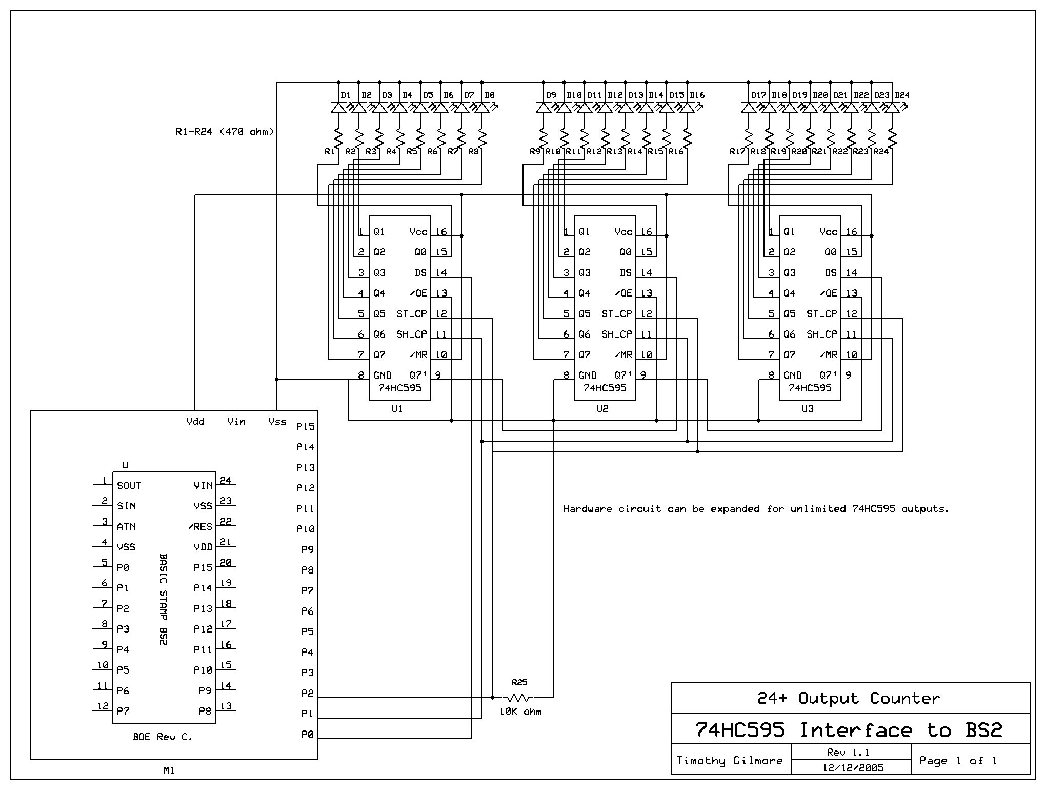
I have modified my 8255 output sequence counter BS2 code for the 74HC595. It only uses·3 BS2 pins (vs 11 for the 8255). This means it can be expanded to sequence count·with adding·more 74HC595s.
The code has 2 subroutines that will forward sequence count·the LEDs or reverse sequence count the LEDs.
It is fairly clean and straight forward.
Attached you will find the BS2 code, hardware circuit and 74HC595 datasheet.
Let me know what you think. If there is any interest I can convert this for use with the SX28 fairly easily.
Thanks,
Timothy Gilmore
Post Edited (tdg8934) : 12/12/2005 10:45:15 PM GMT
pdf
141K
Comments
If you wanted to cascade multiple 595's you would only need 3 I/O lines.
I/O #1 - Keep all of the SH_CP's together (Shift Register Clock Pulse)
I/O #2 - On the first 595 connect only the DS (Serial Data Input)
I/O #3 - Wire all of the ST_CP's together (Strobe "Latch" Clock Pulse)
To cascade multiple 595's connect Q7' (pin 9) of the first stage to DS (pin14)
of the second stage... and follow this pattern for any additional stages.
Once ALL shift registers have been loaded, pulse the ST_CP to update the data
on the output lines.
Check this method that I used almost 10 years ago that allows you to cascade multiple
inputs over a 4-conductor (telephone wire)....
webpages.charter.net/schwabelove/BasicStamp/OctalSerialCascade.gif
▔▔▔▔▔▔▔▔▔▔▔▔▔▔▔▔▔▔▔▔▔▔▔▔
Beau Schwabe
IC Layout Engineer
Parallax, Inc.
Post Edited (Beau Schwabe (Parallax)) : 12/11/2005 5:25:28 AM GMT
The original Stampworks expanded outputs program that you are refering to only allows 8 outputs (1 74HC595) to be controlled at a time or independantly from the other 74HC595 shift registers from what I can tell·witht the stampworks code as it only uses 1 pattern statement (e.g. pattern = %00000001). It shifts the bits in from the first 74HC595 to the last (or perhaps vice versa) but anyway with only using 1 pattern statement you will see·2 or more·sequence countings or forward and reverse LED patterns on each individual 74HC595 showing each·(2·or more)·8 output pattern instead of (1) 24 output forward and reverse LED pattern.
However, as not to appear argumentative, I will re-look into the original stampworks expanded outputs design to see the possiblity in modifying the code to allow for (1) 24 output control of LED patterns (using 3 shift registers). It just was not apparent to me yesterday.
PS: In my circuit, the DataOut and Clock lines are tied together, but the latch lines had to be separate otherwise only a slight LED flash was seen to appear flickering. The Q7' line did not appear to be needed in my design so it was not. Anyway, I will get back to this post later this morning.
Thanks,
Timothy Gilmore
Post Edited (tdg8934) : 12/11/2005 1:19:25 PM GMT
I believe my design is a good one for sequencing through 24+ outputs.
Timothy Gilmore
▔▔▔▔▔▔▔▔▔▔▔▔▔▔▔▔▔▔▔▔▔▔▔▔
Sid Weaver
Do you have a Stamp Tester yet?
http://hometown.aol.com/newzed/index.html
·
All the files are posted in the original 1st post.
Timothy Gilmore
I hope you don't mind, that I modified your original code... below should be a functional equivalent using only 3 I/O's
▔▔▔▔▔▔▔▔▔▔▔▔▔▔▔▔▔▔▔▔▔▔▔▔
Beau Schwabe
IC Layout Engineer
Parallax, Inc.
Post Edited (Beau Schwabe (Parallax)) : 12/11/2005 10:12:05 PM GMT
Sid
I appreciate the new code. However, there may be a problem with your Out_Forward subroutine. Did you hardwire it together and test it first?
When I run it...it first cycles between the first and the second LED for 24 counts and finally runs the reverse routine correctly starting at the 24th LED and cycles back to the first.
Let me know what you find. It looks fine to me but you may want to test it.
Thanks again,
Timothy Gilmore
Actually, no I didn't hardwire it, but I did test the logic flow. Perhaps I missed something in the translation.
The "pattern" is just that anyway, the "Heart" of the program only requires a few lines of code...
In this configuration, the patterns could be anything... for example if you designed a clock,
the patterns could be the result from a lookup table that corresponds to the appropriate 7-segment
LED to light. If you needed more than 3 595 IC for more outputs, simply add another line...
▔▔▔▔▔▔▔▔▔▔▔▔▔▔▔▔▔▔▔▔▔▔▔▔
Beau Schwabe
IC Layout Engineer
Parallax, Inc.
http://forums.parallax.com/showthread.php?p=552892
You simply SHIFTOUT 3 bytes, the PULSOUT your latch.· This provides 24 outputs, which in this case are driving a·BINARY LED Display.
▔▔▔▔▔▔▔▔▔▔▔▔▔▔▔▔▔▔▔▔▔▔▔▔
Chris Savage
Parallax Tech Support
csavage@parallax.com
I know there is a problem with·Beau's code·that he·posted. I have rebuilt the stampworks expanded output design (23b) which is the really the same as·Beau's AND the link presented by Chris. Understanding this design is NOT the issue. It is well posted. However, the issues are 2 fold.
First the method I designed with used more than 1 latch line. Whether it can be with 3 lines total or not, I was only posting my method that worked for me. I do very much appreciate any and all sugestions. As part of Beau's code does work (Out_Reverse subroutine) this tells me that it can be done with 1 latch line which is good news·but just a different way to do it than mine.
Second is that I did test Stampworks expanded output (23b) code on your design and it does work well cycling through 8 leds for EACH 74HC595 in forward and reverse. However, when Beau's code is run (as stated before) it cycles through 2 LEDs back and forth 24 times and then runs the Out_Reverse subroutine and then repeats the entire process as there is a Goto Main statement.
If it is possible someone else·should hardwire up something and test Beau's code to·verify my results as I already have twice in different wiring schemes (took DataOut, Clock and Latch from the first 74595 the first time and took the same signals from the last 74595 and the 2 LED cycling problem followed the change I made) using the your design.
As a Lead Test Engineer, I whole heartedly believe in testing a product fully before it is released in all aspects of hardware, software and data.
I am just asking if someone else would wire Beau's or Chris's circuit (the same)·and run Beau's code (suspected problem) and verify my findings.
Thanks,
Timothy Gilmore
Since the I/O real-estate on the Stamp is very high, I simply wanted to offer a solution using a minimal amount of pins.· It's not that any one design is better than the other, we have
all seen that there are always many solutions to a given problem.· The code that I submitted was based on your original code that turned on the first led, and cycled all the way down
to the 24th led and back to the first led again.· Since I didn't have any 595's at my disposal, I simulated the logic flow in the forward direction only.· Later I manually translated the
forward code to operate in reverse.· (Scratching my head) I'm surprised that forward has a problem.· I would expect that if there were a problem it would be in the reverse.
I·certainly don't doubt your findings; If I can scrounge up a couple of 595's then I will re-visit my error.· Humans make mistakes, and last I checked I was definitely human.
▔▔▔▔▔▔▔▔▔▔▔▔▔▔▔▔▔▔▔▔▔▔▔▔
Beau Schwabe
IC Layout Engineer
Parallax, Inc.
As long as you have the LSBFirst and MSBfirst commands correct, then shifting (on the BS2 part) should happen just as prescribed.
This project is connected to a PC through the Serial Port.· If you send the BS2 the ascii character "!", then the BS2 will display a "$" figure on the 10x14 LED Display.
The LEDs are controlled by 3 74595s, and have current drivers.
This is functional code for MY application, but I wanted to show it to you as a functional model.
Post Edited (Steel) : 12/12/2005 9:20:21 PM GMT
I have attached them in the original post and removed the original drawing and code.
Thanks to all - Especially Beau!
I too have a 140 LED matrix. I have attached a drawing for you to review. It sounds like it may be the same thing if you have·7 negative signals going to the amplified rows and·20 positive signals going to the amplified columns.
I too am trying to display letters and symbols (as I figured out·how to scroll)·I would like to try a static·display but my current LED matrix can only display 4 (5 column) characters.
I have examined your code but don't see where you have the rows going to.
I would like·more info if you·can provide it on your process / design.
Thanks,
Timothy Gilmore
Post Edited (tdg8934) : 12/12/2005 11:30:45 PM GMT