Shop OBEX P1 Docs P2 Docs Learn Events
www.batchpcb.com — Parallax Forums

www.batchpcb.com

Paul BakerPaul Baker Posts: 6,351
edited 2005-12-06 04:51 in General Discussion
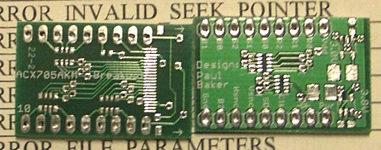
Sparkfun's PCB service is back up and doing weekly runs. I got a design in thier first week online, and the results are pretty good. I've included a photo of the front and back of the board for forum members to look at, the edge solder pads are standard 0.1" spacing to give you an idea of the scale of the board. A couple·things I've noticed is that the silk screen layer is not automatically masked out on the solder pads, so it will print right over a pad, the amusing thing is that one of the boards printed right over the pads while the other was moved out of the way, all from the same gerber file. The other thing is that the shear is not perfect, one of the boards extends beyond the shear border by about 0.5mm in one corner. All in all not bad for a prototype board service charging a $10 processing fee + $2.50 /in2. Also the processing fee is per order, so you can submit multiple designs and/or copies for just the additional $2.50 /in2 fee.

www.batchpcb.com

▔▔▔▔▔▔▔▔▔▔▔▔▔▔▔▔▔▔▔▔▔▔▔▔
·1+1=10
777 x 306 - 77K

Comments

  • ForrestForrest Posts: 1,341
    edited 2005-12-06 02:19
    .5 mm (.020 in) is a typical finished board size tolerance for PCB production lots. As for the legend being printed over pads - if that's where you designed it then that's where the board manufacturer will place it. It's up to you to fix this problem when you design the legend.
  • Paul BakerPaul Baker Posts: 6,351
    edited 2005-12-06 03:02
    The text in the silkscreen layer in the gerber did not sit over any solder pads, but it is my experience that board houses aren't as critical in placement or font size since it is only the legend. Other houses such as Advanced Circuits do a very good job of preventing the silkscreen layer from ending up on the solder pads even when you place text directly over them (it simply doesn't print on the pad but does anywhere the pad isn't). Im not bitching, Im happy with the result, and will sand the silk screen off the pad before soldering. I am only communicating my experience since people on the forums have expressed an interest in the service, but noone had a sample board to show what quality the service provided.

    ▔▔▔▔▔▔▔▔▔▔▔▔▔▔▔▔▔▔▔▔▔▔▔▔
    ·1+1=10
  • ForrestForrest Posts: 1,341
    edited 2005-12-06 03:33
    Ah, so the board manufacturer goofed-up. Legends are hard to align without some sort of common reference point on the board. You might try putting a 2 round fiducials (.040 in round pad with no hole) near opposite diagonal corners - in the same location on all the layers (circuit, solder mask, legend). That way it will be easy for the board manufacturer to easily line all the layers up.

    What's the SMT pitch on your board - looks pretty small. What's the board going to be when it's assembled?
  • Paul BakerPaul Baker Posts: 6,351
    edited 2005-12-06 04:05
    Good idea about the alignment, most of the parts are either .5mm or .65mm, though I discovered I purchased the wrong resistor arrays for the back-side. I hate that, since Ill have to spend $5 handling fee for an under $25 order plus the shipping cost for a $1 part (Digikey). Know of any other major parts distrutors that have no small order handling fee?

    The board is a breakout board for the Sony color LCD from Electronic Goldmine, the board provides the 3.0V and 3.8 V required and 5V->3V resistor dividers for all the signal lines.

    ▔▔▔▔▔▔▔▔▔▔▔▔▔▔▔▔▔▔▔▔▔▔▔▔
    ·1+1=10
  • ForrestForrest Posts: 1,341
    edited 2005-12-06 04:51
    Looks like an interesting project. I assume you're talking about the SONY ACX705AKM. I almost bought that display the other day but decided I should actually start finishing some of my old projects before buying parts for the next project!
Sign In or Register to comment.