I am a bit confused on this DAC chip
Since I was cleaning up my play area and found this tube of DAC0800's I thought I would give it another go to see if i could hook it up and make it work.
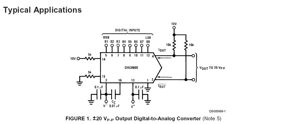
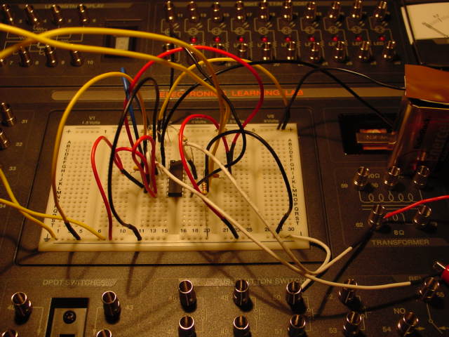
AS you can see it looks like a mess. I have 9 volts instead of 10 volts on pins 14, 4 and 2 and I have another battery connected to the +9 I am using for using for those inputs to get +18 volts for pin 13.
I am confused with a few things.
1. It says it is a current output chip
2. the diagram shows a Vout to 20 Vp-p
3. The arrows on pins 4 and 2 point into the chip
So with that said, its hooked up,
I hooked up pins 5,6,7, and 8 to +4 volts to make them HIGH
I hooked up pins 9,10,11,and 12 to Ground to make them low
I then measured the voltage on pins 4 and 2 making each pin from 12,11,10, and 9 HIGH
Results are
Pin 256 1 2 4 8 Digital Byte Value
12
0 | 1 | 0 | 0 | 0
11
0 | 0 | 1 | 0 | 0
10
0 | 0 | 0 | 1 | 0
09
0 | 0 | 0 | 0 | 1
1. 3 1.63 1.59 1.56 1.56 Volts measured for Byte values 256, 1, 2, 4, and 8
Could someone tell me what I should be measuring and how i should measure voltage or current. I just dont get what this thing does.
http://www.national.com/ds/DA/DAC0802.pdf
Hmmm After reading a tad more I see the figure I posted below , the 10k resistors are a simulated load for a typical application I shall endever to measure the voltage across them in the same manner as I did above to see what happens.
Nope, just 6.9 volts measured across both of the 10k resistors, no change when setting any pins high or low.
▔▔▔▔▔▔▔▔▔▔▔▔▔▔▔▔▔▔▔▔▔▔▔▔
Think outside the BOX!
Post Edited (metron9) : 12/3/2005 5:59:08 AM GMT


Comments
Also, you'll need to change your VCC and VEE.
You can use a 741 for the op-amp.
The DAC address bits should·each be pulled high (= 4.7K·to 10K), with your DIP switch (?) taking the input low.
I've included the DAC0808 datasheet (I think they're all the same, operationally --·basically differences in accuracy.)
▔▔▔▔▔▔▔▔▔▔▔▔▔▔▔▔▔▔▔▔▔▔▔▔
When you get 1st Place in the "Darwin Awards", you're a Winner & a Loser.
▔▔▔▔▔▔▔▔▔▔▔▔▔▔▔▔▔▔▔▔▔▔▔▔
Think outside the BOX!