

Basic stamp and dc motor driver SN754410
 Duc Le
Posts: 8
Duc Le
Posts: 8
Hi,
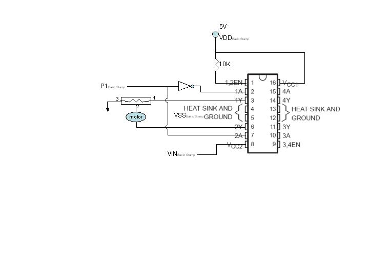
Iam using the Basic Stamp 2px (with the Board of Education) with the SN754410 to control a DC motor to do the following:
1.· able to vary the speed with the my trimpot
2.· switch the rotation direction with a mechanical switch but I am not sure which switch and how to connect it to the circuit.· Any suggestion?
I also attached a schematic for clarification.· I really appreciate your help.
Thanks
Duc
408-623-1913
720 x 540 - 17K
Comments
·· If that's a potentiometer you have connected there I hope it can handle the current/power of that motor.· Typically they cannot.· You wouldn't normally connect a potentiometer in this manner.· It would actually be a rheostat.· Even this isn't the typical way to control the motor.·
▔▔▔▔▔▔▔▔▔▔▔▔▔▔▔▔▔▔▔▔▔▔▔▔
Chris Savage
Parallax Tech Support
csavage@parallax.com
Post Edited (Chris Savage (Parallax)) : 11/22/2005 9:21:18 PM GMT
Thanks for replying. What would be the right way to connect rheostat or potentiometer?
▔▔▔▔▔▔▔▔▔▔▔▔▔▔▔▔▔▔▔▔▔▔▔▔
Chris Savage
Parallax Tech Support
csavage@parallax.com
I have modified the design a bit and attached is a new schematic. Basically, I still have the mechanical switch to control the direction and RC timer (with variable resistor) to alter the speed. I am still unclear how to use the RC timer and convert that into PWM to control the speed. I did a little test on my RC timer with the following code:
' {$STAMP BS2px}
' {$PBASIC 2.5}
time VAR Word
DO
HIGH 7
PAUSE 100
RCTIME 7, 1, time
DEBUG HOME, "time = ", DEC5 time
LOOP
I got some number from 0 to 1,000. Now how do I use this number to convert that to PWM? Thanks very much.
·· After looking up this device I realized it is similar to the L293 and thus it is merely a Push-Pull driver.· You can actually get motor direction control from this chip.· But for speed control you will need a PWMPAL or similar device to drive the inputs properly.· Now, to use the RCTIME function you have for control, you will need to find the range of values you send the driver chip from the PWMPAL or whatever device you use, and scale the range accordingly.
▔▔▔▔▔▔▔▔▔▔▔▔▔▔▔▔▔▔▔▔▔▔▔▔
Chris Savage
Parallax Tech Support
csavage@parallax.com
Thanks
▔▔▔▔▔▔▔▔▔▔▔▔▔▔▔▔▔▔▔▔▔▔▔▔
Chris Savage
Parallax Tech Support
csavage@parallax.com
checkPot:
PWM pin, duty, cycles
HIGH 1 'put current out to the capacitor
PAUSE 1 ············ 'hold a millisecond
RCTIME 1,1, potVar 'RCTIME to get a value for potVar
byteVar = (potVar/10000) * 255 'create byteVar, 0-255, that varies with potVar
PWM 9, byteVar, 10 'pulse-width modulate pin 9, voltage = byteVar, for 10 milliseconds
GOTO checkPot
2.· I am having some problems with the running the program.· Error message: NO Basic Stamp Found.· I tried to debug the USB driver and it seemed to be OK.· I restart my computer and it didn't help.
Thanks very much for following through
1. I am using the RCTIME (RC timer circuit)
checkPot:
PWM pin, duty, cycles
HIGH 1 'put current out to the capacitor
PAUSE 1 'hold a millisecond
RCTIME 1,1, potVar 'RCTIME to get a value for potVar
byteVar = (potVar/10000) * 255 'create byteVar, 0-255, that varies with potVar
PWM 9, byteVar, 10 'pulse-width modulate pin 9, voltage = byteVar, for 10 milliseconds
GOTO checkPot
2. If I set a pin HIGH, that' means I get +5V out. Then I stick one wire from the DC motor to that same pin and the other to VSS, but somehow the motor doesnt' run. what does that mean?
The Basic Stamp pins were never intended to drive anything like a motor load. The total capacity of any single Stamp pin is in the neighborhood of 25-30 mA.
Now, as to what this means:
1. The Basic Stamp is incapable of providing the necessary current to drive your motor directly. This design limitation is also true of most micro-controllers and micro-processors.
2. If the Stamp pin was subjected to such an overload, for any length of time, without a current limiting resistor, that Stamp pin may have been BLOWN OUT, or will be soon!
3. Either use a motor driver chip, or at least a drive transister to take the load of the motor. The Stamp pin drives the transistor (very little current required) and the transistor controls the motor.
Regards,
Bruce Bates
' {$STAMP BS2px}
' {$PBASIC 2.5}
potVar VAR Word
Speed VAR Word
main:
HIGH 1 'put current out to the capacitor
RCTIME 1,1, potVar 'RCTIME to get a value for potVar
Speed = (potVar/1000) * 255 'create byteVar, 0-255, that varies w/ potVar
PWM 9, Speed, 70 'pwm pin 9, voltage = byteVar, for 10 milliseconds
IN15 = Speed
DO
IF IN14=1 THEN 'Spin the motor cw
HIGH 12
LOW 9
ELSEIF IN14=0 THEN 'Spin the motor ccw
LOW 12
HIGH 9
ENDIF
LOOP
GOTO main