

Maybe i Originally Posted this Wrong, I want to control 2 RGB Matrix of leds 5
 DigitalDj
Posts: 207
DigitalDj
Posts: 207
Hello,
What would be the best way to control a matrix of RGB leds·5 x 16 for a total of·80 individual x 2 matrix's.
How hard would this be to program with RGB? Is there a way to setup programming with the SX's for matrix's?
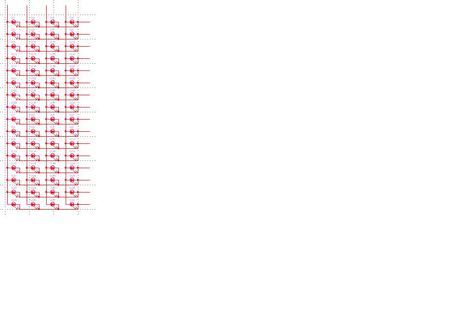
The drawing shows a 4 x 16 which i changed to 5 x 16 RGB and wanting to use 2 of these. I want the RGB to be controlled by PWM. What i am wanting to find out is if 1 SX28 can do 1 bank of the RGB matrix or possibly both. I will need it setup the chip for serial input and addressable if i have to use more than 1 chip.
Jon suggested looking at the Robo Olymics schematic which i did but would need to modify it considerably to do what i want. The robo Olympics Badge is setup for text which is something i would eventually want my matrix's to do but will there be a memory constraint on the SX28 to do everything for example, text, serial input, addressable and PWM on 8 outputs.
Thanks,
Kevin
Post Edited (DigitalDj) : 11/19/2005 11:14:23 PM GMT
What would be the best way to control a matrix of RGB leds·5 x 16 for a total of·80 individual x 2 matrix's.
How hard would this be to program with RGB? Is there a way to setup programming with the SX's for matrix's?
The drawing shows a 4 x 16 which i changed to 5 x 16 RGB and wanting to use 2 of these. I want the RGB to be controlled by PWM. What i am wanting to find out is if 1 SX28 can do 1 bank of the RGB matrix or possibly both. I will need it setup the chip for serial input and addressable if i have to use more than 1 chip.
Jon suggested looking at the Robo Olymics schematic which i did but would need to modify it considerably to do what i want. The robo Olympics Badge is setup for text which is something i would eventually want my matrix's to do but will there be a memory constraint on the SX28 to do everything for example, text, serial input, addressable and PWM on 8 outputs.
Thanks,
Kevin
Post Edited (DigitalDj) : 11/19/2005 11:14:23 PM GMT
962 x 652 - 44K
Comments
http://www.parallax.com/detail.asp?product_id=28099
▔▔▔▔▔▔▔▔▔▔▔▔▔▔▔▔▔▔▔▔▔▔▔▔
Jon Williams
Applications Engineer, Parallax
Thanks,
I printed out the schematic for the badge to look at.
Do you know when the new SX28 experimenter boards are due out?
In the SX badge is there enough pins left to make the chip addressable like chip 1,2,3 etc. for using multiple chips?
Kevin
▔▔▔▔▔▔▔▔▔▔▔▔▔▔▔▔▔▔▔▔▔▔▔▔
Jon Williams
Applications Engineer, Parallax
1. Is it possible to make the chip and program so that i can use multiple chips(addressable).
2.·How about adding·pwm and serial input?
3. Would there be enough memory on the chip? If not i guess i could do·the matrix text programming·from the computer which may be better and more user friendly.
4. What is the long connector off of the processor for?
I can always keep the same led layout as the badge i will just have to do some measuring and reconfiguring on my modules i have designed. If i keep the same led layout as the badge this will give me better look(resolution) since there is more leds.
I like the idea of the badge becuase now i could run messages across my matrix.
Thanks,
Kevin
Post Edited (DigitalDj) : 11/18/2005 4:09:59 AM GMT
2. Yes, you could do that too.· It would take some work, but it's possible.· You'd probably have to have a carefully-crafted ISR that handles looking at the PWM input, the serial input, and maintains the display multiplexing.· I wrote a simple LED multiplexer in SX/B for Nuts & Volts (Januray 2005) that you might use as a starting point.· It shows how to receive serial in the ISR and multiplex a bunch of 7-segment displays.
3. I don't know -- that would depend on your specific requirements for buffering the serial input and display.
4. That's the SX-Key connector so you can reprogram the badge.
▔▔▔▔▔▔▔▔▔▔▔▔▔▔▔▔▔▔▔▔▔▔▔▔
Jon Williams
Applications Engineer, Parallax
http://forums.parallax.com/showthread.php?p=558939
I am using currently using a 74HC595 to drive the ULN2003 to the LED's. However, the Robolympics badge circuit uses 4028 (BCD to Decimal Decoder) which I don't have and not available at Radio Shack. I could order it online and I may very well do that later (+ pay shipping and time to wait). However, I do have 74HCT138 (3 inputs) and·74??04 inverters·which may turn it into a 4028 (4 inputs). I may be able to modify the SX28 code then.
Is it worth it to go this route (74HC595 or (74HCT138 w/ 74??04 inverters)) or just wait and order the 4028's?
Thoughts ... comments.
Timothy Gilmore
▔▔▔▔▔▔▔▔▔▔▔▔▔▔▔▔▔▔▔▔▔▔▔▔
·1+1=10
I call a truce.
Here is a program I write some time ago that will control 64 LED with PWM control. I never tested it, and I don't really have time right now. Maybe if someone else is interested in doing the same thing they could try it out. It is based on the 16 channel PWM program I posted quite some time ago on the SX forum.
Bean.
▔▔▔▔▔▔▔▔▔▔▔▔▔▔▔▔▔▔▔▔▔▔▔▔
"SX-Video·Module" Now available from Parallax for only $28.95
http://www.parallax.com/detail.asp?product_id=30012
"SX-Video OSD module" Now available from Parallax for only·$49.95
http://www.parallax.com/detail.asp?product_id=30015
Product web site: www.sxvm.com
Those that would give up freedom for security will have neither.
▔▔▔▔▔▔▔▔▔▔▔▔▔▔▔▔▔▔▔▔▔▔▔▔
·1+1=10