

Measuring wheel speed and acceleration with a BS2
 winchman
Posts: 22
winchman
Posts: 22
I want to use a microprocessor (MP) to monitor the speed and acceleration of the drum on a special purpose winch I build. The winch is used to apply tension to a nylon line about 1800 feet long. There is considerable stretch in the line when it's under tension. The MP will be used to monitor the rotation of the drum, apply the drum brake when the tension is nearly gone, and then release the brake when the drum is stopped. If the braking isn't applied at just the right time, the line will be tangled in a "bird's nest" as centrifugal force forms loops of loose line. The braking force will be provided by applying power to the winch motor for just long enough to stop the rotation of the drum. The winch is designed to have the minimum number of mechanical components - the motor and drum - and relies on the operation of the MP to function properly.
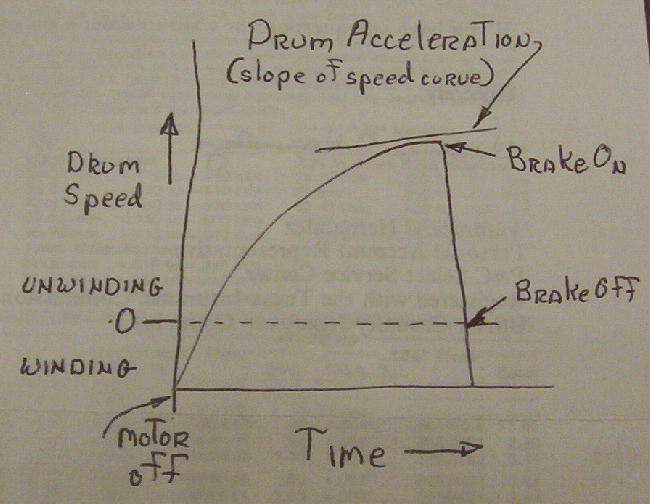
The MP will only be operating for several seconds after power is removed from the motor. During this time the drum will be accelerating from near 0 to an estimated 2000 RPMs as tension on the winch line is relieved by spooling out line. The rate of acceleration gets lower as the tension is relieved.
The speed of the drum and the time elapsed can vary widely, but the best time to apply the brake will always be when the slope of the speed curve is approaching 0. The drum must be nearly stopped when the brake is released. I've attached a graph.
I plan to mount two magnets on the side of the drum, and use a hall effect sensor to provide input to the MP.
Will the BS2 (with proper programming, of course) be able to analyze the string of pulses from the sensor to determine when to apply and release the brake?
Roger
Post Edited (winchman) : 11/16/2005 9:12:24 AM GMT
650 x 504 - 49K
Comments
I think the BS2 could do this fairly easily.
1. Use a loop that checks to see if the hall effect sensor is activated. A schmidt-trigger can clean up the signal if its too messy. Could be one second loop or less depending on the optimum numbers you are looking for.
2. count how many time the sensor is activated per loop. This gives "RPM" (actually RPS) whichever works better.
3. send an on or off signal to the brake at the specific "low" RPM (RPS?)
4. you may even send a signal to suppress the motor from going on until the brake is released.
5. conversly you would'nt want the motor _and_ break on at the same time either.
Just some thoughts.
Setting up a wheel and pressure sensor to measure the tension of the line directly.
I want to get rid of the bar, rotary solenoid, and belt to make the winch mechanically simpler. I can apply power to the motor just long enough to stop the drum, instead of using the belt. It'll only take a fraction of a second, because the motor is very powerful (about 2kw).
The winch as shown works VERY well. It's the best one I've built. See others here:
http://photobucket.com/albums/1003/winchman/ I'm looking for the last little bit of performance and mechanical simplicity by using a microprocessor.
I'm confident I understand the physics involved, and I know what the microprocessor has to do, but I've never worked with them, and I don't know the language or programming. I've ordered some books, a development kit, and some other stuff to get me going. I was just looking for a little reassurance that I was heading in the right direction. I know I've got a lot to learn.
Roger
Post Edited (winchman) : 11/17/2005 6:15:08 AM GMT
I'm gradually absorbing the details of your project. I see an extension cord in the pic, I assume for the rotary solenoid. Is the main motor AC or DC? Also, if the motor is DC, is it a permanent magnet type?
What I'm thinking is that you would monitor the motor terminal voltage while freewheeling or otherwise not under power, do some calcs to get speed, acceleration, etc. Then, at the proper time, apply reverse voltage for a predetermined time to stop things. Its not as accurate as a proper tachometer, but given that the idea is to minimise components, it might be workable.
As for switching the motor current, you can go the bang-bang route of relays and/or braking resistors, or an H-bridge solid state solution.
Cheers
Inside the control box are two relays and some capacitors to control the braking solenoid and the clutch between the motor and drum.
The motor is an automobile starter motor fitted with dual ball bearings. I also use PM motors, but they're much more expensive, and not as powerful as the wound-field type.
The winch in the attached picture has a PM motor. The motor is used to provide braking by shorting out the armature when required. That's why there's no belt or rotary solenoid. The control box is behind the motor.
Programming a microcontroller for a winch with a PM motor would be simpler, because the brake can just stay "on" after the drum stops. But I want the microprocessor to work with the wound-field motors, which I'm more likely to be using.
The big battery for running the winch is mounted in the truck bed, out of the picture. There are two auto starter solenoids in series (a safety precaution) at the battery to switch the motor on and off. The solenoids are connected to a footswitch, which is tapped during winch operation to control the tension on the line.
I've written out what I think I need the microprocessor to do. It's certainly not code, but it helped me think clearly about the operations that need to done. It's just time measurements, comparisons between time measurements, and comparisons between time measurements and setpoint values. There's only one input from the hall effect sensor, and one output that goes hi and then low. Here it is, followed by a short explanation.
I plan on having a half second delay after the winch motor is turned off. That will keep from having the microprocessor go through repeated resets as the power is turned on and off during winch operation. After the delay, power will be supplied to the microprocessor.
1. Power on
2. Measure time interval between consecutive pulses and store value
3. Measure time interval between consecutive pulses and compare to stored value
a. If interval is larger, shut down [noparse][[/noparse]larger interval indicates drum is slowing, broken line condition]
b. If interval is smaller, store new value and proceed [noparse][[/noparse]normal condition]
4. Measure time interval between consecutive pulses and compare to stored value
a. If difference is greater than setpoint A value, store new value, and repeat step 4
b. If difference is less than setpoint A value, initiate braking, then proceed
5. Measure time interval between first and second pulse and compare to setpoint B value
a. If less than setpoint B value, repeat step 5
b. If greater than setpoint B value, terminate braking, then shut down
Steps 2 and 3 are to make sure something isn't amiss. If the drum is slowing down after half a second, a shutdown is the best thing to do.
In step 4, it's comparing the time intervals between pairs of consecutive pulses to determine if the acceleration is still above a certain amount. The brake must come on just before the speed curve becomes flat, so there will still be a little acceleration. I don't care how fast it's going, I want to know how rapidly the speed is increasing. It won't increase much if the tension is getting low.
Step five is comparing the time interval of two consecutive pulses to determine if the drum is nearly stopped. The preferred time for the brake to go off is just before the drum is stopped.
All of this will take place in 1 to 4 seconds, depending on the winch and a bunch of other variables.
Roger
As far as I can tell from reading magazines and looking at the glider forums, my clutch winches are a truly original design. Letting the drum freewheel lets the line go slack VERY quuickly, since the heavy armature (usually about 4-5 pounds) doesn't have to spin up. The drum itself only weighs about 2 pounds. The line goes slack in a half to a third of the time it takes on conventional winch. It's almost scary to watch it go from zero to about 2000RPMs and then to a complete stop, all in two seconds.
It took some time to get the prototype working, but the other four haven't required any tweaking in the design. I untangled about a dozen big bird's nests on the prototype, though.
Roger
▔▔▔▔▔▔▔▔▔▔▔▔▔▔▔▔▔▔▔▔▔▔▔▔
·1+1=10
The permanent magnet motors make surprisingly effective brakes when the armatures are shorted.
Roger
OK, I guessed the glider application. Just need a few more details:
I assume the line is strung out and hooked to glider. Then the winch is powered up to wind the line in and launch the glider.
At some point the glider over-runs the winch and the drum is allowed to run free until the line disconnects. How does the motor/drum clutch engage/disengage?
If you go with reversing the motor voltage to act as a brake, and you're using the series wound motors, some surgery will be required on the motors to bring out the ends of the series fields in order to reverse them with respect to the armature. Then, a few contactors and speed sensing, as has been suggested, should give you what you want.
Interesting project.
regards
The faster the line can go slack, the less speed and altitude the plane will lose while the tension is being relieved. The plane is actually pulling the drum up to speed in the outbound direction, so it's better for the drum to have less resistance and inertia. That's the reason I started putting an electric clutch (from an automobile airconditioner compressor) between the motor and drum.
When power is applied, the motor will always (try to) run in the take-up direction. When it's time to begin braking, the drum will be turning in the outbound direction. By engaging the clutch and applying power to the motor, I take advantage of the inertia of the armature (it's heavy and there's brush drag, too), and also use torque from the motor to stop the drum. Power will be applied to the motor only long enough to bring the drum to a stop. I don't want it to reverse direction, and start taking up line. It will be OK if the drum is turning slowly in either direction, as long as it's not enough to get the loose line tangled.
I won't need to modify the windings or connections to the motor. It only needs to produce torque in the take-up direction. I'll have the microprocessor operate the same pair of solenoid relays that the footswitch is connected to. I really don't need to change much on the winch to use the microprocessor, other than removing the brake belt, rotary solenoid, and the bar that rides on the line. That's the beauty of it, I get a winch that's much simpler mechanically, and it works even better than it does now.
Is there an accepted abbreviation for "microprocessor"?
Based on my description of what I want the microprocessor to do, is this an easy, average, difficult, or really hard program to write?
Roger
Generally "MCP" is understood as an accepted abbreviation for microprocessor, although I'm sure there will be some who disagree.
Regards,
Bruce Bates
I use uC for microcontroller and uP for microprocessor.
Very interesting project, be sure to keep us up to date on it.
Bean.
▔▔▔▔▔▔▔▔▔▔▔▔▔▔▔▔▔▔▔▔▔▔▔▔
"SX-Video·Module" Now available from Parallax for only $28.95
http://www.parallax.com/detail.asp?product_id=30012
"SX-Video OSD module" Now available from Parallax for only·$49.95
http://www.parallax.com/detail.asp?product_id=30015
Product web site: www.sxvm.com
Those that would give up freedom for security will have neither.
·
I'd rate this a simple to average system. The only thing requiring a bit of experimentation will be the speed sensing.
I'd be pleased to help if you get bogged down.
Cheers
Knowing the proposed system isn't in the really hard category makes me feel better. This is my first venture into uPs or MCPs. I wasn't hoping for a trip to the moon, but a good launch would be nice.
Roger
I was initially thinking the model was on a track of some sort horizontal to the ground and at the moment the model reached the winch the cable would disenguage but after looking at the hookup I would guess the model is pulled like a kite and then the pin disenguages.
This brings me to the proposition that a new type of hookup pin could be designed using a microprocessor in the model. Monitoring the tension on the line you could have a pin in the model pull back to release the cable automatically.
1. Pin closed (waiting for launch)
2. Tension increases to some maximum (winch launching model)
3. tension falls to near zero (apex of flight)
4. pin releases cable
5. Pin fails to release OOPS!
6. failsafe, design pin the same way it is now, add the release switch using a small breakaway string that holds the pin to the cable (So during proper function you retreve the pin on the end of the cable)
My mind is just rambeling on....
▔▔▔▔▔▔▔▔▔▔▔▔▔▔▔▔▔▔▔▔▔▔▔▔
Think outside the BOX!
http://static.rcgroups.com/gallery/data/500/7716mono.mpg
It's not my winch or my plane, but it gives the general idea of how it goes. The video is from out in the field toward the turnaround pulley. That plane probably weighs about five pounds, and the wingspan is about eleven feet. The final altitude is about seven hundred feet.
Some people use servo actuated towhooks that release on command. I don't like the added weight and complexity, and I've seen them fail to open too many times.
Another way to get the line off is to dive near the top of the launch, then pull up very sharply. The line is nearly parallel to the fuselage when they do that, so the line slides off despite the high tension. It's a high-G (probably well over 10G) maneuver, and the planes I like to fly won't take the stress.
I've seen people land planes with the winch line still caught in a releasable towhook that didn't work. You're OK as long as you fly in a circle keeping the line slack. Once the line goes tight, the plane arcs over, and accelerates downward. I've seen the wings fold on the way down, too. Bummer.
The largest plane I've launched with one of my winches weighed ten pounds and had a wingspan of 178". The winch motor was from a starter for a 454 cubic inch V8 engine.
Roger
1. Line is tensioned and aircraft is positioned for flight
2. Magnetic clutch is engaged
3. Winch spins up to launch aircraft
4. Aircraft reaches apogee of arc and magnetic clutch is released to allow cable spoolout
5. Aircraft disengages from cable
6. Magnetic clutch engages drum to motor
7. Drum brakes to a stop to prevent rats nest
If this is the proper launch sequence then you will have 2 cycles of the drum in each launch spool up to speed to launch, spool down as aircraft reverses drum rotation to take out line and then spool down again after line release. Drum never needs to be powered in the outbound direction as the aircraft performs this function. Sooo
What may be a simple solution and add some extra features would be to drive the motor 1/4 bridge PWM since it needs only be power in one direction. Once PWM driven it would allow you to add features to the launch such as an·adjustable launch speed ramp and adjustable braking force.
Proposed launch cycle
1. Tension line as normal (possible additional footswitch for line takeup at low motor power)
2. Foot switch activates launch sequence
3. Stamp or SX spins motor up from 0% to 100% power over adjustable time period
4. 1/2 second after footswitch release Stamp or SX releases clutch for overflight of pulley and spoolout
(1/2 second delay allows manual modulation of speed)
5. Second foot switch·re-engages clutch and applys braking sequence/power to motor
6. land safely and repeat
On thinking about the launch cycle it "may" be possible to gain more altitude simply by releasing and engaging the clutch during the launch sequence.
Tension cable
release (aircraft popsup)
loop
I'm not that familiar with glider flight so I could be totaly wrong there. The approach above adds one switch and removes the pulley speed monitoring hardware. However it does add one extra switch for the braking sequence so this may or may not be acceptable but should totaly eliminate the rats nest problem. Even if you desire to monitor drum speed for totaly automated braking I think the PWM addition would be a valuable feature.
Post Edited (ChrisP) : 11/19/2005 4:04:07 PM GMT
Part of the problem is that these motors draw a LOT of current under load. The minimum is probably 100 amps, and the max for a large winch is around 800 amps. I just don't see being able to afford electronic switching for currents that high.
Every pilot I have been around can be expected to forget the winch exists as soon as the plane is off the line. His ONLY concern is flying the plane. Most would walk away even if the winch was in flames. They'd just deal with it later.
That being the case, the winch has to be completely automatic from the time the pilot takes his foot off the switch until the drum is stopped. Contest winches are different in that they have an attendant to make sure the line is retrieved properly, and the winch is ready for the next launch. My winches are only for the sport fliers.
The idea about using a uP for improving the operation of the winch during the launch itself is very appealing. The best thing it could be programmed to do is "pulse" the motor on and off to control the tension during the launch. That would let the pilot select the desired tension, and just step on the switch until he wanted to come off the line.
I can envision that working by monitoring the current flowing to the motor, and interrupting it for a set time if it went too high. That gets a little complex for the real world, though, since the amount of line on the drum depends on where the winch is set up. Some fields are longer one way than the other. The amount of line on the drum affects the relationship between torque (current) and tension. The attached pic shows something I designed to overcome that problem. The narrow section of the drum is a storage area for "extra" line. The "working" section always has just a few wraps at the start of the launch, regardless of the field size. The winch always has the same "feel", and the motor current vs line tension relationship is always the same.
With a divided drum, using a uP for controlling line tension is a realistic possibility. The program could also monitor the drum to determine how much line had been spooled in and adjust the profile as the launch progressed. It's a great idea for development after I get the braking sorted out.
On a windy day, it's possible to get some extra altitude by releasing the clutch, letting line spool out, then engaging the clutch again. You have to be careful not to let the line go slack, or it will come off the plane. It's called "kiting".
Roger
Now for the wild shot in the dark on the electronics approach because of the amperage involved. I'm guessing that either 8-10 could be hung from one output pin of a Stamp or SX or they could be driven from a solid state switch like a MAX326 or possibly an opto isolator that was in turn driven by an output in PWM. I think to PWM a motor though you have to either run a motor mind or switch to an SX and run on interupt to read the speed and drive the motor off of the same microcontrol. This is where my experience and lack of in depth knowledge hurt and where I usually break out some hardware and start tinkering. For line load you could probably maintain the spring loaded micro switchto an input line·to control torque, there has to be an angle to keep it right at the point of switching back and forth. Hold it at a balance point. If so that would give you a constant force. Someone else please feel free to step in and tell me that I'm way off on the electronics side, this is where I go to trial and error, in my application the current load was low so I just went way over rated.
Stopping the drum takes place after they've finished using the winch. They don't care how it's done, as long as they don't have to untangle line before the next launch.
I'll need some help in picking something to go between the uP and the solenoid relays I'm using. There are two of them, and each one draws just over 3A. There's quite a spike from the coil when the field collapses, but I'm pretty sure I can put some small diodes across the terminals to take care it, if necessary.
What should I be looking for to drive the relays? It only needs to come on once for a second or less during each launch cycle.
I've attached a picture of the footswitch I'm using now. It has two microswitches, one for each solenoid relay. (You can just barely see the top of the roller of the second switch toward the right end of the curved support.) They close at slightly different times as the pedal is depressed. That protects one of the solenoids, since there's no current flowing as the contacts close and open. With such high currents and the many on and off cycles during a launch, the solenoid contacts sometimes weld themselves together. That's REALLY bad for the plane AND the winch. Having two solenoid relays, and having them close at different times provides a big safety factor.
Roger
You may want to "instrument" a winch with various sensors--RPM, motor current, etc. and collect some real world data.
Another approach to this problem might be to measure the line tension indirectly. When there is tension in the line there is a sideways force acting on the spool/winch assembly directed toward the turnaround pulley. The assembly could be designed so that it can slide, pivot, tilt a small amount when the line is under tension and a spring, gravity, etc. would cause it to move in the other direction. Alternatively, a strain or force sensor could then be used to measure the force at the spool axle or other mounting point (could be useful to regulate line tension).
I've observed the following:
1. For a given set-up (distance to pulley and line strength), the time is nearly the same regardless of the amount of tension on the line. This makes sense, because an increase in tension would cause an corresponding increase in acceleration.
2. Depending on the set-up, the line can go slack over a wide range of drum speeds that makes it impractical to have the brake come on at a particular speed.
3. Depending on the set-up, the line can go slack over a range of elapsed times that makes it impractical to set fixed time period before the brake comes on. Actually the range is very narrow, but since the whole thing takes place in about 2 seconds, a tenth of a second makes a big difference in performance.
During a launch, tha amount of line spooled up can vary widely, depending on the weight of the plane, the wind, and how the pilot flies the plane.
Any fixed settings of time or drum speed would rarely give optimum winch performance, and there's always a chance the settings would be wrong, and the line would get tangled. Plus, I don't want to have an adjustment on the winch that the pilot has to set each time he changes line or changes the distance to the turnaround pulley, or flies a different plane.
The system I'm using now senses line tension directly with a bar riding on the line. It works very well regardess of the distance to the pulley, line strength, plane, wind, or any other variable. It gets the brake on just as the line is about to go slack. It takes less than a pound of tension to lift the bar, and a pound of tension will easily turn the drum. I haven't had a line tangle as a result of improper operation of the winch in years of flying and thousands of launches with all sorts of planes. The few tangles I have had were my fault, mainly forgetting to put the bar down on the line when I set up the winch, or not noticing that the wind had blown the line out from under the bar. Maybe that explains why I want to get rid of that stupid bar so badly.
Like I said earlier, what I've got now is really good, but I'm looking for the last iota of performance from the winch and a way to make it mechanically simpler.
The physics of the situation tells me there's a direct relationship betwen line tension and the acceleration of the drum, so I should be able to determine the tension by determining the drum's acceleration. I can do that by measuring how fast it's going now, and comparing that to how fast it was going just a little while ago.
Roger
Your first post said the drum reaches an estimated 2000 rpm. Your last post said you need a reaction time in less than 0.1 seconds. This kind of perfomance should easily be handled by a BS2. You could measure the time between hall-sensor pulses or count the number of pulses during a time interval.
By instrumenting the winch, I mean adding the magnets and hall sensor as you stated in you earlier post, as well as a sensor/switch to tell when the brake has been applied using your current setup. A program in the BS2 has a loop that measures the drum rpm, checks to see if the brake has been released, and sends the data to a laptop, PDA, etc. You can then analyze the data to determine a good criteria for your final program to engage the brake.
That looks simple enough. I believe the 1N4001 diode is something I've used before to absorb the spike from the collapsing coil. I guess I'll need a small "project" board to put that circuit on, and run some jumpers to the output pins. That won't go on the BoE itself, will it?
Can I connect both fets to one output pin? Or, will I need to have the program go hi on two output pins at the appropriate time?
Based on your description, I won't need a relay to isolate the fets from the two solenoid relays when they are being operated by the footswitch. That's nice. The solenoid relays close at different times when the winch is being operated with the footswitch, so I can't have them being driven from the same fet.
I suppose I can put the fets and diodes on a "project" board (from Radio Shack?), and just run a jumper to the output pin(s) on the BoE.
I may have to modify the schematic a little. One side of the relay coil is grounded to the mounting bracket, and I can't change that. I've attached a sketch of what I think would work. I just moved the relay to the other side of the fet, and added the input (+12 volts) from the footswitch. Will that work?
Where's a good place to shop for the components? Radioshack doesn't list the IRLZ44, but they do have a TIP3055 - NPN Transistor, which looks similar. Would that work?
http://www.radioshack.com/product/index.jsp?productId=2062611&cp=2032058.2032230.2032279&parentPage=family
There's a RS about five minutes away, so shopping there is convenient.
Thanks for the help.
Roger
Post Edited (winchman) : 11/21/2005 8:12:06 AM GMT
That's right, except I need to have the "brake on" setpoint just a little before the tension gets to zero. At high speeds, the centrifugal force overcomes the tension, and throws the line out into loose loops.
"This kind of perfomance should easily be handled by a BS2. You could measure the time between hall-sensor pulses or count the number of pulses during a time interval."
I was hoping I could measure time between pulses. It doesn't need to be "real" time, just something consistent that I can count and compare.
"By instrumenting the winch, I mean adding the magnets and hall sensor as you stated in you earlier post, as well as a sensor/switch to tell when the brake has been applied using your current setup. A program in the BS2 has a loop that measures the drum rpm, checks to see if the brake has been released, and sends the data to a laptop, PDA, etc. You can then analyze the data to determine a good criteria for your final program to engage the brake."
I think I can come up with a laptop. Being able to see what the BS2 is seeing and doing will help a lot. I can set the winch up for some very realistic tests without actually launching a plane, and the place I can do that isn't very far from home. Once I make a few test runs to see if the system actually works, it shouldn't be too hard to adjust the setpoints for best performance. Of course, actual launches will be the last test. By then I want a fair amount of confidence in the system.
I expect to get the stuff I ordered this week. I'm really looking forward to getting started. Meanwhile, I'm working feverishly to complete my other winch project.
Roger
Oh, as far as switching one output then the other, no worries it happens fast enough to appear simultaneous even to your winch.