

Beginner needs help with H-Bridge
 Strommy
Posts: 5
Strommy
Posts: 5
Hello all,
First off since im new to these forums i'd like to introduce myself so you know my capabilities. My name is Eric and im currently a junior in H.S. Im taking an electronics votech class and it inspired me to get into robotics. I know most the basics but some of this robotics stuff is really confusing. And so my question...
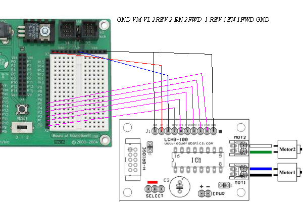
The kit I decided to start off with was the Rogue ATR kit from Rogue Robotics. I find it to be a good kit except the documentation is kind of lacking. So i've been digging and digging and have come up with a theory as to how this H-Bridge operates. I made a picture to describe it and I was hoping you guys could ok it and give me some reccomendations. The picture is attached to this post.
Also, here is some links as to how I gained my current knowledge of this.
http://roguerobotics.com/index.php?module=documents&JAS_DocumentManager_op=categories&category=20
http://www.hobbyengineering.com/appHBridge1A.html
One more question. I'm getting confused by the power source things with the BS2. I know VDD is +5V and VSS is ground. However, VIN confuses me. With this can I plug any power source into it under 26v (I think thats what I read) to power the whole board? Can I plug a power source into VIN and the 9V battery slot or just one?
Help is greatly appreciated.
First off since im new to these forums i'd like to introduce myself so you know my capabilities.
My name is Eric and im currently a junior in H.S. Im taking an electronics votech class and it inspired me to get into robotics. I know most the basics but some of this robotics stuff is really confusing. And so my question...The kit I decided to start off with was the Rogue ATR kit from Rogue Robotics. I find it to be a good kit except the documentation is kind of lacking. So i've been digging and digging and have come up with a theory as to how this H-Bridge operates. I made a picture to describe it and I was hoping you guys could ok it and give me some reccomendations. The picture is attached to this post.
Also, here is some links as to how I gained my current knowledge of this.
http://roguerobotics.com/index.php?module=documents&JAS_DocumentManager_op=categories&category=20
http://www.hobbyengineering.com/appHBridge1A.html
One more question. I'm getting confused by the power source things with the BS2. I know VDD is +5V and VSS is ground. However, VIN confuses me. With this can I plug any power source into it under 26v (I think thats what I read) to power the whole board? Can I plug a power source into VIN and the 9V battery slot or just one?
Help is greatly appreciated.
bmp
703K
Comments
·· Welcome to the forums.· I'm not sure about your Rogue Robotics Motor Controller, but I can help you with your voltage (Vin) questions.· First of all, the connectors for the Battery and DC Plug prevent you from using both at the same time.· They are mutually exclusive and cannot both be used at the same time.· Quite simply they are connected together, so if you put a battery on there and you could somehow get a DC adapter on there, it would be connected in parallel with the battery, which isn't a good thing.
·· Now, as for the maximum input on the Vin.· It should never exceed 15 volts maximum, but your board clearly states 6-9 volts input.· This is to protect you if you should have an unregulated power supply, which, when unloaded can have a much higher output.
▔▔▔▔▔▔▔▔▔▔▔▔▔▔▔▔▔▔▔▔▔▔▔▔
Chris Savage
Parallax Tech Support
csavage@parallax.com
For my money, Rogue IS treating you (the user) pretty badly in the documention department, as you said! You will probably find it real handy to have the Manual and/or the Schematic for the Parallax Board of Education nearby for reference. here is a link where you can download those items for FREE, from Parallax:
http://www.parallax.com/detail.asp?product_id=28150
They could have provided that link as easily if I did, even if they didn't want to keep that documentation on their server.
When asking for help here on the Parallax forum, it is important for us to know that the Rogue ATR Kit is set up to use the Parallax Board of Education (as they do note in their limited documentation), although the photo was helpful. The more specific information you can provide, generally the faster and more completely your questions will be answered.
Chris has answered your questions about powering that board, so I'll say no more there.
It's not clear what specific information or questions you have regarding the H-Bridge. Rogue offers an H-Bridge suitable for, and designed around, that Tamiya Dual Motor setup they offer, and provide limited documentation for it as well. So too as you have noted, the Hobby Engineering web site has additional and more complete information on that very same H-Bridge. Is it the theory of H-Bridge construction or operation that you are lacking? If so, just head for your favorite search engine, as I did, and enter "h-bridge theory of operation" and something like the following link will be returned:
http://www.dprg.org/tutorials/1998-04a/
Regards,
Bruce Bates
So basically if I were to use a battery pack, I would need to get a DC plug for it to power my board. I read that the BS2 uses anywhere from 4.3V to 4.6V during operation so 15-4.6 would mean id have 10.4 volts left to use on other items in my robot?
I understand the whole theory behind it and how it works, it's hooking it up I don't understand. I wanna be sure I do it right before blowing $150 before seeing my robot move hehe. The best I came up with was that image I made and the program for operation is on Hobby Engineering. (God bless them)
Thanks again guys.
▔▔▔▔▔▔▔▔▔▔▔▔▔▔▔▔▔▔▔▔▔▔▔▔
Chris Savage
Parallax Tech Support
csavage@parallax.com
' {$STAMP BS2}
' {$PBASIC 2.5}

' SN754410 Demo Program #1
'
' This program exercises motors attached to a SN755410NE H-Bridge IC.
' It simply runs the motors full speed in one direction for a period of time,
' pauses and repeats in the opposite direction.
'
' This program assumes the simplist possible hardware implimentation so three
' Basic Stamp I/O pins are required for each motor.
'
' The support routines assume that the three connections for each motor are
' made sequentiantially along one side of an APPMOD connector.  That results in
' the numeric sequence of the pins being a sequentional count by two.  The first
' Basic Stamp pin number is the Motor ID and is connected to the enable pin
' for that motor on the h-bridge.  The next Basic Stamp pin (Motor ID + 2)
' is connected to the h-bridge "on" pin for the forward direction.  The last
' pin is connected to the h-bridge "on" pin for the reverse direction.


MotorID VAR Byte        ' Current Motor ID
Motor1  CON 1           ' Motor 1 control on stamp pins 1, 3 and 5
                        ' SN754410 pins 1 (1,2EN), 2 (1A) and 7 (2A)
Motor2  CON 2           ' Motor 2 control on stamp pins 2, 4 and 6
                        ' SN754410 pins 9 (3,4EN), 10 (3A) and 15 (4A)

  DEBUG "Forward"
  MotorID = Motor1
  MotorID = Motor2
  GOSUB MotorForward

MotorForward:
LOW MotorID + 3
LOW MotorID
The bot slowly roles forward from this code but I can't see how. I also figured out a left and right turn but I cannot find a way to get them to work with the forward code. In other words, I try to add a pause after the forward code and then a left turn but it only keeps rolling forward. Any suggestions?
Also, I purchased a 9.6V NiCd battery and put a DC plug on it. I plug it into my BoE and turn the power on and the green LED lights up but when I try to upload to the BS2 it can't find the stamp. Then when I switch back to the wall pack ot works just fine.
Thanks in advance
Eric
I'm not sure what your controller is doing- but most controllers take a signal/command, and continue to run that until they get a new command.
Now looking at the code you have posted:
You set MotorID to Motor1, then to Motor2. So the motor forward sub only sees the value of "Motor2" in the subroutine.
I would suggest getting the structure of your controller/bridge under your belt first, then building up the PBASIC code.
Ryan
▔▔▔▔▔▔▔▔▔▔▔▔▔▔▔▔▔▔▔▔▔▔▔▔
Ryan Clarke
Parallax Tech Support
RClarke@Parallax.com