Hello:
I would like to interface a LC circuit to the Basic Stamp. How do I do it ?
Do I need another circuit between this one and the Stamp?
Do you have a any similar circuit or example i can used ?
Thanks,
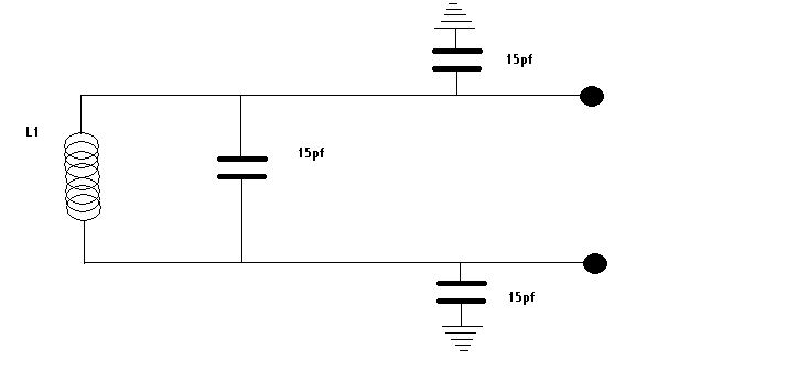
(this is the LC circuit I would like to used)


Comments
▔▔▔▔▔▔▔▔▔▔▔▔▔▔▔▔▔▔▔▔▔▔▔▔
Beau Schwabe
IC Layout Engineer
Parallax, Inc.
detector, or are you building a sort of BS2 based grid-dip meter? Do you know what inductive values
or ranges you have?
There are other ways to do this, but here is an example of a Metal Detector.
Stamp Based Metal Detector
This is a "copy" of an old web page that I used to manage....
Beau's Old Web-Page
...See "Coil/Inductor Reader"
...and "multiple Inductor Reader (LVDT example)"
▔▔▔▔▔▔▔▔▔▔▔▔▔▔▔▔▔▔▔▔▔▔▔▔
Beau Schwabe
IC Layout Engineer
Parallax, Inc.
Thanks a lot for the information.
It is a metal detector ...but for a musical instrument.
On your Coil/Inductor reader you used a Schmith trigger IC and then a Binary counter. Can we go directly from the 74HCT14 and 'count' that signal with the Stamp II?
Thanks
▔▔▔▔▔▔▔▔▔▔▔▔▔▔▔▔▔▔▔▔▔▔▔▔
Jon Williams
Applications Engineer, Parallax
This circuit was designed a few years ago, when there was only one BS2 option.
Even so, the frequency from the 74HC14 is going to be a couple of MHz... I don't
think a newer BS2 by itself will be fast enough. The 4040B brings the frequency
down to a workable level for the BS2.
Note: Use a 74HC14 rather than a 74HCT14... The difference is in the input, one
is TTL level and the other is CMOS level. The "non" TTL produces more of a
square wave on the output.
Question:
Are you trying to detect a string vibration such as that on an electric guitar?
▔▔▔▔▔▔▔▔▔▔▔▔▔▔▔▔▔▔▔▔▔▔▔▔
Beau Schwabe
IC Layout Engineer
Parallax, Inc.
Very clever. Well sort of a theremin. I just got some information on the workings of an instrument built by Thermen. It was called the theremin cello. It works by inductance changes in a coil. So my idea is to built this electronic instrument and interface to the Stamp II and translate those values to MIDI (which I have done before)-> a MIDI theremin cello (or violin or bass).
The "coil" will be a very (very) long coil.(representing the string of the instrument)[noparse][[/noparse]maybe the metal string of guitar or electric bass might work] The Inductance changes will be done by touching the coil at certain points. Luckily this changes can be translate to a frequency (from the 74HC14) and read by the STAMP II.
Thanks
With the subject of coils and inductors, you actually caught me at a good time.
On the side (when my electrical checks in layout are running) I am currently working
on an application with a new design approach that senses the inductance changes
in a coil. ... So basically inductors are fresh in my mind at the moment.
May I ask how long is "very (very) long" and how exactly will you be
"touching the coil at certain points"?
▔▔▔▔▔▔▔▔▔▔▔▔▔▔▔▔▔▔▔▔▔▔▔▔
Beau Schwabe
IC Layout Engineer
Parallax, Inc.
Lets say a 30 inches long coil (it will be a plastic (?) tube wound with copper wire. The contact will be done with a very flexible wire (or wire mesh).
▔▔▔▔▔▔▔▔▔▔▔▔▔▔▔▔▔▔▔▔▔▔▔▔
Chris Savage
Parallax Tech Support
csavage@parallax.com
▔▔▔▔▔▔▔▔▔▔▔▔▔▔▔▔▔▔▔▔▔▔▔▔
Chris Savage
Parallax Tech Support
csavage@parallax.com
My first thought is that a 30 inch coil would have a really large inductance value.
...looking at a few things around here that I could build one of these with.
1" PVC pipe
large spool of #22 insulated solid hook up wire
....Hmmm ok so the PVC actually has a diameter of 1-1/8" and at a rough estimate
the #22 wire with insulation has a pitch of 18 turns per inch.
18 turns per inch at 30 inches equals 540 total turns with a mean radius of 0.5625 inches.
Reference (inductance calculator):
http://forums.parallax.com/showthread.php?p=557406
See "CoilCalc_XLS.txt"
for a "single layer wound air coil"
L = ( ( r * N ) ^2 ) / ( ( 9 * r ) + ( 10 * l ) )
where:
r = the mean radius (inches)
N = number of turns
l = length (inches)
For L, I get about 300uH
Reference (Resonant Frequency Calculator)
www.deephaven.co.uk/lc.html
...Use this to play with various capacitor values.
▔▔▔▔▔▔▔▔▔▔▔▔▔▔▔▔▔▔▔▔▔▔▔▔
Beau Schwabe
IC Layout Engineer
Parallax, Inc.
I just caught something in your post that I should point out....
"The Inductance changes will be done by touching the coil at certain points"
In a tuned LC when you touch the coil what you are changing more
than inductance is the capacitance. Unless you are made of metal, touching
the coil has very little effect on the actual inductance value.
▔▔▔▔▔▔▔▔▔▔▔▔▔▔▔▔▔▔▔▔▔▔▔▔
Beau Schwabe
IC Layout Engineer
Parallax, Inc.
▔▔▔▔▔▔▔▔▔▔▔▔▔▔▔▔▔▔▔▔▔▔▔▔
Chris Savage
Parallax Tech Support
csavage@parallax.com
Yes the flexible metal strip will be touching the wire wound pipe (the coil) at certain point. If the flexible metal strip is connected to the circuit, then will it change the coil length (at the moment of contact) and change the inductance ?
Again·thank you·(to ALL) for your help.
Hmmmm
▔▔▔▔▔▔▔▔▔▔▔▔▔▔▔▔▔▔▔▔▔▔▔▔
Beau Schwabe
IC Layout Engineer
Parallax, Inc.
▔▔▔▔▔▔▔▔▔▔▔▔▔▔▔▔▔▔▔▔▔▔▔▔
Chris Savage
Parallax Tech Support
csavage@parallax.com
Based on my earlier calculation that a 30 inch coil with 540 turns
of #22 solid insulated hookup wire wrapped around a 1 inch PVC
would yield an inductor of about 300uH, here is an idea that might
be more effective than trying to measure subtle inductive changes.
At the risk of sounding like Nicola Tesla, you can apply the basic
principle to your coil that applies to a Tesla coil.
 In >----o----[noparse][[/noparse]Coil]----o----> Out
         |              |
       [noparse][[/noparse]Cap]          [noparse][[/noparse]Cap]
         |              |
GND >----o--------------o----> GND
With a Coil value of 300uH and Capacitor values of .1uF
(something easy to find) the resonate frequency is going to be
about 29kHz.
Note: In the schematic above In and Out can be interchanged.
Now, if the circuit is in tune and you apply a 1V p-p sine wave
at the input that has a frequency of 29kHz the voltage potential
between the Input and the Output can be in excess of 250V p-p!!!!
Keep in mind that this voltage is without any kind of load and is
very low current, it is however still present.
Now you say, how can I apply this to my project....
Well, when you "touch" the coil at various locations ( as you indicated
you will have a wand of sorts... this is actually perfect). you effectively
create a voltage divider with the coil. What's nice is that you don't
need to be in direct contact with the coil windings, the capacitance
between the insulation on the coil windings and your "wand" will be
enough so that you should be able to get a voltage reading between
the "wand" and ground. By loading the Input an Output with a resistor
( Start in Meg Ohm range ) you can bring down the voltage potential
to a more manageable level. ...Or you can slightly detune your coil by
changing the input frequency. You will want the input frequency to be
adjustable anyway.
▔▔▔▔▔▔▔▔▔▔▔▔▔▔▔▔▔▔▔▔▔▔▔▔
Beau Schwabe
IC Layout Engineer
Parallax, Inc.
Calculated Inductance: 300uH
Actual Inductance: 325uH
I changed the capacitor values from 0.1uF to 220pF. This increased
the resonate frequency to about 595kHz. With the circuit below, I
measured about 100V directly across the coil. When measuring with
the "wand" to GND I measured a proportional voltage from 35V down
to 0V depending on where the "wand" was on the coil.
Tuning:
By placing my hand on the "high-side" of the coil, I tuned the variable
resistor, looking at the scope, until the voltage level peaked and was
stable. (About 100V Pk-Pk)
▔▔▔▔▔▔▔▔▔▔▔▔▔▔▔▔▔▔▔▔▔▔▔▔
Beau Schwabe
IC Layout Engineer
Parallax, Inc.
I will have to try this myself as soon as possible.
Question: You apply a sine wave signal to the coil/capacitor section. Will it work without such signal or by applying the +5v ?
I read thru your notes about voltage of 100v to 35v. I am only a novice on electronics but for sure this will kill the Basic Stamp right away. Some kind of optoisolator might be in order. Right? (even using resistors as you point out - the voltage potential is there so an error will be a disaster)
Thanks,
A sine wave is ideal, but a square or triangle will also work. ....at 595kHz off of a 74HC14, a square wave almost
looks like a sine wave.
100v is what you see directly across the coil...35V is what is capacitively coupled through the coil to the "wand" without actually touching the coil.
What I used for a "wand" was to connect the wand terminal to my thumb like a ring, and then I used my entire
hand to wrap around the coil as if holding a tennis racket. By moving my hand back and forth applying various
amounts of pressure on the coil, I could predictably change the output voltage.
This is relatively low current (less than 3mA @ 35V) .... I have added a circuit to condition the output
so that an ordinary ADC, or a scheme similar to that used in my Stamp based metal detector should be able
to read the voltage without any problems.
▔▔▔▔▔▔▔▔▔▔▔▔▔▔▔▔▔▔▔▔▔▔▔▔
Beau Schwabe
IC Layout Engineer
Parallax, Inc.