

My TIP120 I getting HOT
 metron9
Posts: 1,100
metron9
Posts: 1,100
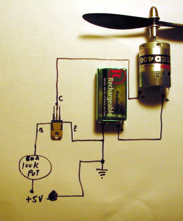
This circuit works but the TIP120 Darlington Transistor gets very hot when running. The motor stays very cool
Please tell me why with reference to the Voltage/Current specs. Is this just a wrong way to do this?
Post Edited (metron9) : 11/10/2005 7:10:52 AM GMT
Please tell me why with reference to the Voltage/Current specs. Is this just a wrong way to do this?
Post Edited (metron9) : 11/10/2005 7:10:52 AM GMT
Comments
Looks like you're operating the transistor inthe linear region. Its more usual to control motor circuits by using the transistor as a switch, as in fully on or fully off.
What you want to do is drive the transistor base with a pulse width modulated signal. Then, the transistor will be switched quickly on and off which will make the motor think the average voltage is varying and change its speed accordingly. The transistor will thank you by not having to dissipate the IR drop within it.
Just Google PWM for some sample circuits and more explanantion.
http://www.discovercircuits.com/M/motor-cont.htm
▔▔▔▔▔▔▔▔▔▔▔▔▔▔▔▔▔▔▔▔▔▔▔▔
-Rule your Destiny-
--Be Good. Be Bad. Be Provas--
▔▔▔▔▔▔▔▔▔▔▔▔▔▔▔▔▔▔▔▔▔▔▔▔
"When all think alike, no one is thinking very much.' - Walter Lippmann (1889-1974)
······································································ Warm regards,····· G. Herzog [noparse][[/noparse]·黃鶴 ]·in Taiwan
▔▔▔▔▔▔▔▔▔▔▔▔▔▔▔▔▔▔▔▔▔▔▔▔
Thanks, Parallax!
▔▔▔▔▔▔▔▔▔▔▔▔▔▔▔▔▔▔▔▔▔▔▔▔
Truly Understand the Fundamentals and the Path will be so much easier...
http://www.tigoe.net/pcomp/code/archives/bx-24/000294.shtml
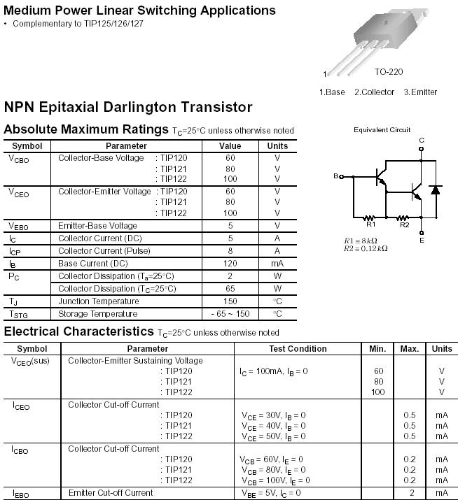
Stamptrol, Yes I understand it should be on or off and partially on creates heat but this is where I fail at knowing exactly where that point is. (reading the datasheet)
The datasheet says Vebo Base Voltage Maximum = 5 volts and Veb(on) = 2.5 volts MAX
It says Ib Base Current DC = 120 mA
So to Drive the base it would seem I need 2.5 volts that can supply 120 mA
The Circuit shows a PIC pin driving the base with a 1kohm resistor, AS I dont understand the resistance value of the Transistor, but evan at 0ohms the 5 volt supply on the pin with a 1kresistor is only allowing 5mA to flow.
Fully on the way I read the datasheet (obviously wrong) , (with about 21 ohms resistance using 2.5 volts ie in my head 21 ohms at 2.5 volts = 119 mA)
So something is not calculating right in my brain, The reason I put the pot on the original circuit is to measure the current while testing to see how much current was flowing when the motor (or LED in the first test) seemed to be fully on.
A quick edit, (i have to get to work) I see others have just posted, I will explore more when I get back home)
Post Edited (metron9) : 11/10/2005 3:24:13 PM GMT
▔▔▔▔▔▔▔▔▔▔▔▔▔▔▔▔▔▔▔▔▔▔▔▔
Thanks, Parallax!
I wish i could make my digital RS meter read more than 200mA but it doesn't seem to work when I plug in the red lead to the 20A current port.
So using 2 tip120 in parallel I would have 10 amps max, in this case
Do I need 2x the base current (a smaller reistor from the logic pin turning on the base?)
I still would like to know how to calculate the FULL ON Base Current, I understand the Voltage to be 2.5 V, but like I said above I just don't see the relationship of the datasheet and the circuit I found that uses a +5 pin and a 1k resistor to drive it.
Just some example math for driving any transistors base is what I am looking for.
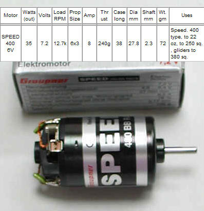
Pulling 8A out of a 9v battery is only give all but a surge.
Now, I learned quite a bit on base voltages, mosfets and darlington arrays tonight. I will say two things before my soldering iron gets hot. (and darn I seem to have actually lost my digital soldering station (my WIFE misplaced it me thinks...)
The use of darlington transistors when run in parallel is not recommended, It is similar to running two LED's in parallel. The one that is cunducting the most takes over and the juce flows through it and not both equally. You can use a feedback resistor to automatically adjust the them to equalize them.
As Kramer said the mosfet is a better choice, and PWM and it works fine when in parallel, I plan to use a resistor on each of the GATES comming from the stamp uC pin. so I bought 2 IRF510's (4 AMP EA and with a pulse that should be fine) and I will hook them up in parallel that is right after I finish soldering my pin connectors to my brushless motor so I can plug it into theESC and look at the sine waves on my scope. This stuff is cool.
I think I can drive the ESC with the same logic as driives the servo motor outlined in the what is a microcontroller book, but I think I may wait to test the signals from a radio transmitter I borrow from my brother unless someone says it's ok to do so, I remember something about not using other servos when putsin with the parallax servo so I will maby not power it up tonight.
I am not shure where all this will take me
I am understanding the charts a bit now oin the datasheets that are in log log format. This gives me a better understanding of what current is needed to turn on full as it relates to the load.
Remember The brushless motor is another project but I added a picture on the original DC brush motor driver and I have of course a new question.
The circuit measures 73 mA draw for the light bulb (light bulb simulating motor load for first test as my motor is not mounted)
I wanted to see if I could measure the current and verify each mosfet takes 1/2 the load.
When I pull one of the source drains and feed it through the meter I get 29 mA
So my question is. To get a more accurate measure of mA flowing through each mosfet (assuming they both cary half of the 73 should read 36 1/2 mA each)
How would one do that to prove each mosfet is carring 1/2 the load?
Some measurements I took
I get 8.41 volts across the lamp when bypassing the mosfets
I get 8.32 volts when going through the mosfets
So the voltage drop across the mosfets is about .09 volts
Measuring across the mosfets I get .12 V so my meter is not so accurate I guess.
Post Edited (metron9) : 11/11/2005 6:10:46 AM GMT
Using a 9.6V external battery + to motor, from - motor to SOURCE of mosfets, and Ground from external battery to ground of the test board.
The motor jumps a tiny amount sometimes when the Gates are held HIGH
I remove the pulldowns and drive the gates ... still nada
I wonder if there is any voltage so I slip in the bulb in series with the motor and yes full brightness.
removing the bulb and having just the motor I turned off the switch that drives the gates HIGH
and touch the grounds together and the motor runs
Turn on power to theGATES and motor goes off?????????????
I am indeed in la la land at this point and in need of some serious help driving a motor with a mosfet.
For example,if a device is to conduct 5 amps in a circuit,then good practice will tell you to use a similar device with 2 times the capacity,in this case 10 amps.This rule violation has been the basis for your troubles.I know from experience that the motor you are using will draw lot's more current than one might expect,especially when loaded.
▔▔▔▔▔▔▔▔▔▔▔▔▔▔▔▔▔▔▔▔▔▔▔▔
Thanks, Parallax!
The MOSFETS (with some gate resistance, as you have) will current share as the load increases. I don't think its worth worrying about at the low levels you see with your test bulb. As you have seen, the internal resistance of your meter on 200mA scale is really affecting the measurements. If you want to confirm the current sharing, get your bulb load up over few amps. To see it with your meter, I think you'll find the fuse for the 20A circuit is separate from the meter fuse.
Your circuit HAS to work, assuming the motor is OK, which it seems to be from one of your posts. At light load it won't be drawing anywhere near 8A so your MOSFETS will be OK.
I use the exact same setup on circuit boards I've been building for ever. So to reiterate:
Battery +pos to one side of motor
other side of motor to MOSFET DRAIN
MOSFET SOURCE to battery -neg
MOSFET GATE pulled down to battery -neg with 15K - 100K (has to be the same -neg as battery)
Now, apply +5 volt to the gate, motor runs
Remove +5 volt and motor stops
Good luck
The Chart in the datasheet for Voltage Gate to Source, Voltage at the bottom, current from drain to source is the vertical scale.
looking across to the 5V intersection I read a bit over 1Amp can flow, (My very first time I actually understand reading the charts thai i usually skip over saying i don't understand them, one of the things I think a full forum catagory should be devoted too)
It shows two lines ,one is at a part temp of 175C then other at 25C
At 175C the lines intersect at about 6 1/2 volts to get 4 amps and about 7 1/4 volts at room temp (my room as it's small ant lots of stuff making heat so Im usually around 25C in there)
So With my little diagram using less than 4.5 volts we see I am only allowing around 500ma to flow as you say. Clearly not enough juce to drive an 8 amp motor
So I need to put higher voltage on the GATE and as the csi inspector says, The question becomes... Where on the datasheet is the maximum voltage that can be applied to the GATE?
.
Man i wish at 48 years old I could go back and finish high school and then go to college but just saying that gives me a lump in my throat because you folks make me feel like I am in college and I don't even have to live in a dorm room!
I think I know why so many college kids party so much, When they learn really cool stuff they just want to celebrate the fact but some of them need feedback loops to stop them from cascading in that direction at an exponential rate.... On second thought a zeiner diode in parallel would do the trick, voltage set by the college dean of course.
Post Edited (metron9) : 11/11/2005 6:28:17 PM GMT
▔▔▔▔▔▔▔▔▔▔▔▔▔▔▔▔▔▔▔▔▔▔▔▔
Thanks, Parallax!
Works just fine even with only 3volts on the base.
It was the very first transistor I hooked up in my quest but in my haste I mixed up the Base and Emitter pins on it.
But of course I am not of the mind to if it works don't fart around with it, I shall continue to examine the how and whys of the many ways of solving a problem and I hope to make many mistakes to learn from.
Thank's Jim
Now I think I will explore the brushless 3 phase motors for a while
Firstly, using two MOSfets in parallel is okay, but two BJTs might be a disaster.
Second, there is an apparent limit of about 10Mhtz with FETs due to internal resistance and capacitances.
Third, in traditional configuration you may have problems due to Miller Effect [noparse][[/noparse]which means that the internal capacitances of the FET create unusual behavior]· While this can be avoided by using a· 'gate follower' configuration, the voltage is restricted to near the level of the actual gate voltage.
Finally the 2n3055 really is a simple way out, but I presumed that this was for a model airplane where you might want the MOSfet for reduced weight [noparse][[/noparse]including less of a heat sink].· Mosfets are doable, but 'The Art of Electronics' has a lengthy explanation.
If you intend to go to 3 phase brushless motors, you will likely be seeing more about MOSfets in sets of 3 which are controlled by a PIC or SX-48.·
▔▔▔▔▔▔▔▔▔▔▔▔▔▔▔▔▔▔▔▔▔▔▔▔
"When all think alike, no one is thinking very much.' - Walter Lippmann (1889-1974)
······································································ Warm regards,····· G. Herzog [noparse][[/noparse]·黃鶴 ]·in Taiwan
Post Edited (Kramer) : 11/12/2005 7:35:09 PM GMT